
AR402 | BUILDING CONSTRUCTION & MATERIALS – VII

UNIT III: ADVANCED STRUCTURAL SYSTEMS
3.1 Introduction and significance
Advanced structural systems are engineered combinations of beams, columns, walls, braces, cores and other elements that efficiently transfer gravity and lateral loads. In high-rise buildings, structural selection influences achievable height, usable floor area, façade geometry, service coordination, construction sequence and occupant comfort.
The central challenge is not merely to support vertical loads: increasing height makes wind response, earthquake performance, overturning, drift and foundation settlement important design considerations.
- Structural safety: reliable and continuous load paths.
- Serviceability: control of sway, drift and vibration.
- Architectural integration: coordinate structure with planning, façades and services.
- Constructability: select systems compatible with materials, equipment and sequencing.
3.2 Structural loads and load transfer
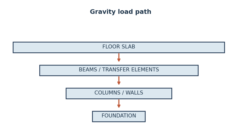
Dead loads arise from permanent construction; imposed loads arise from occupancy and use. Wind generates lateral pressures and dynamic response, while earthquakes produce inertia forces due to ground acceleration. Gravity loads generally pass through slabs to beams or directly to columns/walls, then to foundations and soil. Lateral forces travel through floor diaphragms into cores, walls, frames or braces and finally into the foundations.
3.3 Classification of advanced structural systems
System | Principal lateral-load mechanism | Architectural implication |
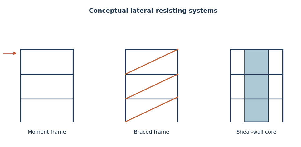
Moment-resisting frame | Bending of beams, columns and joints | Open bays; larger sections at greater height |
Shear wall / core | In-plane shear and flexure | Integrates with lift and stair enclosures |
Braced frame | Axial tension/compression in diagonals | Braces affect openings |
Framed / bundled tube | Perimeter action; interconnected tubes | Strong relationship with façade and massing |
Outrigger and belt system | Core rotation mobilises perimeter columns | Deep structural zones at selected levels |
Diagrid | Triangulated perimeter axial action | Expressive external geometry |
Mega-frame / hybrid | Large primary elements combine systems | Large member and connection zones |
3.4 Moment-resisting frames, shear walls and braced frames
3.4.1 Moment-resisting frame
Rigid or semi-rigid beam–column connections transfer bending moments and shear. Under lateral loading, the frame deforms through bending of members and rotation of joints. Advantages include flexibility in planning and relatively unobstructed bays. Limitations include increasing drift and member sizes as height increases; high-rise frames are therefore often combined with cores or walls.
3.4.2 Shear wall system
Shear walls are stiff vertical planar elements, commonly reinforced concrete, resisting lateral shear and overturning moments. Typical forms include rectangular, L-shaped, U-shaped and coupled walls. Coupled walls use connecting beams to make separate wall piers act together. Positioning should be coordinated with stairs, lifts, corridors and openings; asymmetric arrangements can increase torsion.
3.4.3 Braced frames
Diagonal braces resist lateral loading mainly through axial force. Concentric arrangements include X, V, inverted V and single diagonals. Eccentrically braced frames incorporate yielding links to dissipate seismic energy. Braces are efficient but can interfere with façade openings and circulation. Seismic detailing and brace buckling resistance are essential.
3.5 Structural cores
A reinforced-concrete or steel core frequently encloses elevators, stairs and service shafts. Acting approximately as a vertical cantilever, it resists lateral shear and bending. A well-placed core can provide stiffness and allow open floor plates; very slender buildings may need additional systems. Openings, transfer elements and core eccentricity require structural coordination.
3.6 Tube structural systems
3.6.1 Framed tube
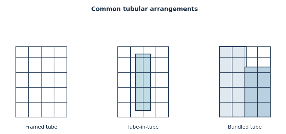
Closely spaced exterior columns and deep spandrel beams form a stiff perimeter frame that behaves approximately as a hollow cantilever. It efficiently engages the building perimeter but may constrain glazing and experience shear lag (nonuniform axial stress in perimeter columns).
3.6.2 Tube-in-tube
An exterior tube and interior core tube act together through floor diaphragms. This combines the advantages of perimeter resistance and a central core, but requires careful analysis of interaction and stiffness.
3.6.3 Bundled tube
Several interconnected tubes form a larger system, allowing tubes to terminate at different heights and creating setbacks. Willis Tower in Chicago is a classic example of the bundled-tube approach.
3.7 Outrigger and belt-truss systems
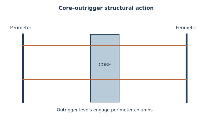
Outriggers are stiff trusses or walls connecting the core to perimeter columns. When the core tends to rotate under wind or seismic loading, perimeter columns develop axial tension and compression that oppose overturning. Belt trusses or belt walls can distribute forces among exterior columns. These systems improve lateral stiffness but may occupy mechanical or refuge-floor zones and demand complex construction sequencing.
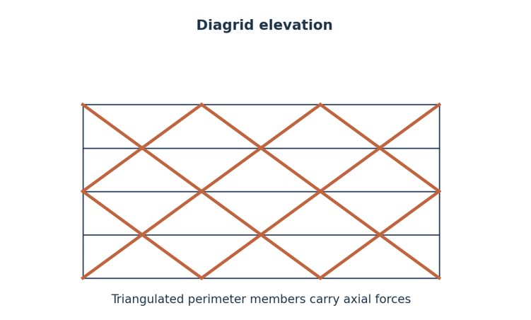
3.8 Diagrid systems
A diagrid is a perimeter network of diagonal members forming triangles. The geometry transfers a substantial share of gravity and lateral forces through axial action, often reducing conventional perimeter vertical columns. Advantages include efficient stiffness and distinctive architectural expression; limitations include complex nodes, fabrication and façade coordination. 30 St Mary Axe in London illustrates an expressive triangulated exterior system.
3.9 Mega-frame and hybrid systems
Mega-columns, mega-braces and large beams or trusses form a primary structural skeleton supporting smaller secondary frames. Hybrid systems combine cores, tubes, outriggers, frames and damping devices to address building-specific requirements. The architect must coordinate large structural elements with usable area, floor-to-floor heights and building services.
3.10 Advanced high-rise construction techniques
3.10.1 Slip-form construction
Slip forms move continuously or near-continuously as concrete is placed and develops sufficient early strength. Suitable for repetitive vertical shafts and cores, they require uninterrupted logistics, controlled concrete setting and rigorous dimensional monitoring.
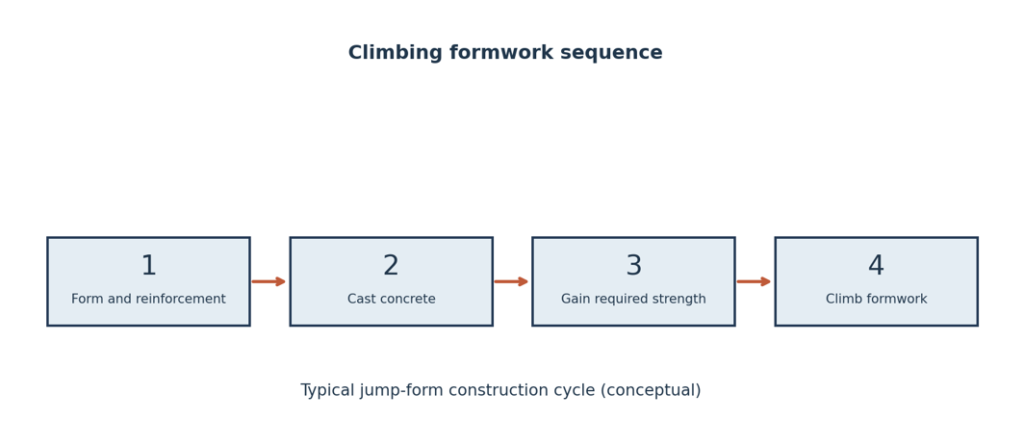
3.10.2 Jump-form and self-climbing formwork
Jump-form systems are repositioned to the next lift after concrete achieves the required strength. Crane-lifted forms depend on crane availability; self-climbing forms use hydraulic systems. Typical cycle: fix reinforcement and embeds; position formwork; place concrete; allow required strength; climb and repeat.
3.10.3 Prefabrication and modular construction
Factory-produced precast columns, beams, slabs, stairs and façade panels can improve repeatability and reduce site operations. Volumetric modules may include finishes and services. Transport dimensions, lifting capacity, tolerances, connections and installation sequence must be addressed early in design.
3.10.4 Top-down construction
For deep basements in dense urban sites, retaining walls and permanent supports are built first, then a ground-level slab is constructed and excavation proceeds beneath it while selected superstructure work may advance. Basement slabs help brace retaining walls; excavation access, ventilation, waterproofing and temporary works become critical.
3.11 High-rise structural behaviour
3.11.1 Wind and seismic action
Wind produces static and dynamic response, including sway, acceleration and occupant discomfort. Earthquakes create inertia forces dependent on mass and ground motion. Earthquake-resistant design requires ductility, continuity, regularity and appropriate detailing—not simply greater stiffness. Structural codes and specialist analysis determine project-specific criteria.
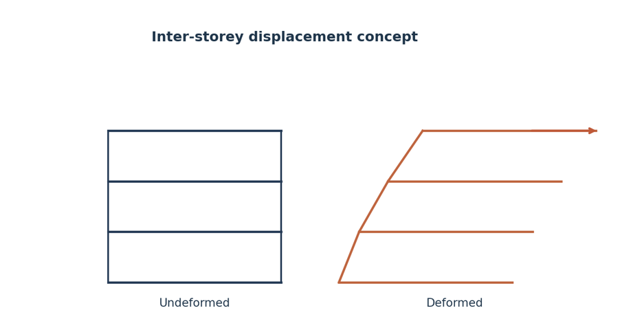
3.11.2 Lateral displacement and inter-storey drift
Lateral displacement is the horizontal movement of a floor relative to its original position. Inter-storey displacement is Δᵢ = uᵢ − uᵢ₋₁, and drift ratio is θᵢ = Δᵢ / hᵢ, where hᵢ is the storey height. Example: 12 mm relative movement over a 3,000 mm storey gives 12/3,000 = 0.004 = 0.4%. This is an arithmetic example, not an assertion of code compliance.
3.12 Foundation systems for tall buildings
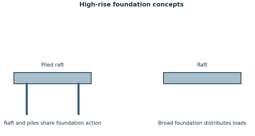
Rafts spread loads over a broad area; piles transfer loads to deeper strata through shaft resistance and/or end bearing; piled rafts use both raft and piles to manage capacity and settlement. Selection depends on soil conditions, groundwater, building loads, basement depth and neighbouring properties. Geotechnical investigation and settlement analysis are indispensable.
3.13 Damping and vibration control
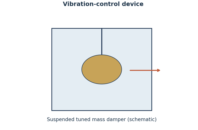
Tuned mass dampers use an auxiliary mass with restoring and damping components to reduce motion near selected vibration frequencies. Viscous dampers dissipate energy through fluid resistance. Base isolation modifies transmission of ground motion but is not automatically suitable for all tall buildings. Taipei 101 is a widely cited example of a building with a large tuned mass damper.
3.14 Architectural selection criteria
Factor | Design question |
Height and slenderness | Is lateral stiffness sufficient for wind and drift control? |
Floor plate and core | Can circulation and services be integrated without loss of functionality? |
Façade | Will braces, tubes or diagrid nodes constrain openings? |
Construction programme | Is the selected formwork/erection cycle feasible? |
Ground conditions | What basement and foundation approach is viable? |
Seismic context | Does the system provide regularity, ductility and continuity? |
3.15 Brief building case studies
Willis Tower, Chicago — bundled tube
Interconnected tubes and differing termination heights show how structure can generate stepped massing.
Burj Khalifa, Dubai — buttressed core
Three wings arranged around a central core buttress one another; plan geometry and structure are tightly integrated.
30 St Mary Axe, London — diagrid expression
A triangulated exterior demonstrates how lateral structural systems can become visible architectural language.
Shanghai Tower, Shanghai — composite and outrigger system
Illustrates coordination among core, perimeter systems, tall-building form and façade.
Taipei 101, Taipei — vibration control
A large tuned mass damper illustrates the importance of occupant comfort and dynamic response.
3.16 Tutorials and practical exercises
- Exercise 1 (A3 sheet): Identify and diagram the structural systems of three high-rise buildings, including a gravity and lateral load path.
- Exercise 2 (A3 sheet): Compare moment frame, shear wall and diagrid using sketches, architectural implications and limitations.
- Exercise 3 (A2 sheet): Develop a conceptual structural grid, core and lateral system for a hypothetical 40-storey commercial tower; annotate the reason for selection.
3.17 Examination preparation
Short-answer questions
- Define shear wall and its role in high-rise buildings.
- What is the purpose of an outrigger?
- Differentiate framed tube and bundled tube.
- Define inter-storey drift.
- What is self-climbing formwork?
- State two architectural implications of diagrid construction.
Descriptive questions
- Explain shear wall, braced frame and moment frame systems with labelled sketches.
- Compare framed tube, tube-in-tube and bundled tube structural systems.
- Describe the working principle of outrigger and belt truss systems.
- Explain slip form, jump form and top-down construction with their advantages and limitations.
- Discuss wind and seismic response and architectural measures for high-rise buildings.
- Using one built example, explain how structural systems influence architectural form.
3.18 Suggested teaching distribution (18 contact hours)
Session | Topics | Hours |
1 | Introduction, loads, classification | 2 |
2 | Moment frames, shear walls, bracing | 2 |
3 | Cores and tube systems | 2 |
4 | Outriggers and diagrids | 2 |
5 | Mega-frames and hybrid systems | 2 |
6 | High-rise construction techniques | 2 |
7 | Wind, earthquake and drift | 2 |
8 | Foundations, dampers, architectural integration | 2 |
9 | Case studies, tutorials and revision | 2 |
3.19 Recommended reading
- Chudley, R. and Greeno, R. Building Construction Handbook. Routledge.
- Barry, R. The Construction of Buildings. Wiley-Blackwell.
- Ali, M. M. and Moon, K. S. (2007). Structural developments in tall buildings: Current trends and future prospects. Architectural Science Review, 50(3), 205–223.
- Taranath, B. S. (2016). Structural Analysis and Design of Tall Buildings: Steel and Composite Construction. CRC Press.
- Smith, B. S. and Coull, A. (1991). Tall Building Structures: Analysis and Design. Wiley.
How useful was this post?
Click on a star to rate it!
Average rating 0 / 5. Vote count: 0
No votes so far! Be the first to rate this post.


