
ARCHITECTURAL DRAWING & GRAPHICS-III

AR203
ARCHITECTURAL DRAWING & GRAPHICS-II
UNIT III
TWO-POINT PERSPECTIVE
Blocks, Curved Surfaces and Residential Applications
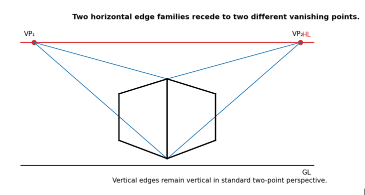
Concept diagram: two horizontal edge families converge towards two vanishing points.
B.Arch. II Year / III Semester | Session 2026-27
Unit III Overview
Prescribed Syllabus |
Unit III shifts from the frontal logic of one-point perspective to corner views in which two principal horizontal directions recede from the observer. The study sequence therefore moves from establishing two vanishing directions to simple solids, composite forms, curved surfaces and finally residential architecture.
Learning Objectives
- Understand the geometric condition that produces two-point perspective.
- Determine two vanishing points from the object orientation and Station Point.
- Construct accurate perspectives of simple and complex blocks using plan projection.
- Develop stepped, recessed, projecting and composite forms without directly measuring perspective depth.
- Construct circles and cylinders in two-point perspective using an enclosing-square method.
- Apply two-point perspective to pavilions, small buildings and residential forms with openings and projections.
- Use line weight, tonal hierarchy and scale references to improve architectural presentation.
Syllabus-to-Study-Note Alignment
Study-note section | Syllabus component | Practice linkage |
3.1-3.4 | Principles and construction method | Master method / Problems 01-02 |
3.5 | Simple blocks | Exercise-book 05; Problems 01-02 |
3.6 | Complex blocks | Exercise-book 06-07; Problems 03-06 |
3.7 | Curved surfaces | Problem 07 |
3.8 | Furniture / architectural element bridge | Problem 08 |
3.9 | Architectural forms | Exercise-book 08; Problems 09-10 |
3.10 | Residences | Problem 11 |
3.11 | Integrated design application | Problem 12 |
3.1 Introduction to Two-Point Perspective
Two-point perspective is a perspective system in which two principal families of horizontal parallel lines recede in different directions and converge towards two separate Vanishing Points, generally located on the Horizon Line. It is most commonly used when an object or building is viewed from a corner rather than directly from the front.
Core Rule |
Two-point perspective is particularly useful for building exteriors because it can show two adjoining façades simultaneously and communicate the mass, depth and corner condition of an architectural form.
3.2 Conditions for Two-Point Perspective
Principal direction | Behaviour in two-point perspective |
Vertical edges | Remain vertical in standard two-point perspective |
Horizontal direction 1 | Converges towards VP₁ |
Horizontal direction 2 | Converges towards VP₂ |
Horizon Line | Carries both horizontal vanishing points |
Nearest corner / vertical edge | Often used as the principal true-height reference when it touches PP |
Object orientation | Usually neither principal horizontal face is parallel to PP |
The number of vanishing points is related to the number of principal spatial directions that recede from the observer, not to the complexity of the object. A very simple block may use two vanishing points, while a complex object can still be constructed from the same two horizontal directions.
3.3 Determining the Two Vanishing Points
The vanishing points are obtained from the plan. For each family of horizontal parallel edges, draw a line through the Station Point parallel to that spatial direction. Where the line meets the Picture Plane gives the plan location of the corresponding vanishing direction; project that point to the Horizon Line to obtain the Vanishing Point.
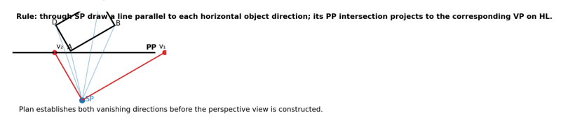
Important Rule |
3.4 Master Construction Method
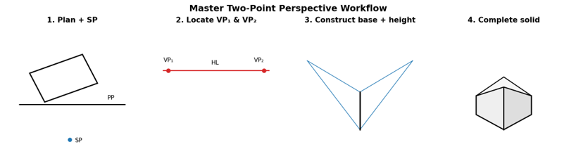
- 1. Draw the Picture Plane and place the object plan in the specified orientation.
- 2. Locate the Central Plane and Station Point at the given distance from PP.
- 3. From SP draw lines parallel to the two principal horizontal object directions to obtain v₁ and v₂ on PP.
- 4. Draw visual rays from SP to every important plan corner; mark their piercing points on PP.
- 5. Draw the Ground Line and Horizon Line according to the given eye height.
- 6. Project v₁ and v₂ vertically to HL to obtain VP₁ and VP₂.
- 7. Locate the nearest ground corner in the perspective field and draw its two receding edges towards VP₁ and VP₂.
- 8. Use vertical projectors from the plan piercing points to locate the remaining base corners.
- 9. Complete the base by joining corresponding directions towards the opposite VP.
- 10. Transfer true height on a suitable vertical edge, preferably one touching PP, then complete the top edges towards VP₁ and VP₂.
- 11. For recesses, steps, openings and projections, locate every important plan point first; do not guess perspective dimensions.
- 12. Keep construction lines light and darken only the final visible edges.
|
Memory Sequence |
3.5 Perspective of Simple Blocks
The rectangular prism is the basic two-point-perspective exercise. Once students understand how a single corner, two edge directions and a true height generate a complete box, the same logic can be reused for most architectural forms.
The supplied exercise booklet includes Exercise 05, a rectangular prism with a 50 mm × 30 mm base and 55 mm height, with one vertical edge in PP and the longer base edge inclined at 45° to PP. This is a direct Unit-III application because the two horizontal edge families recede in different directions.
- Locate the nearest vertical edge and both VPs first.
- Never measure the 50 mm or 30 mm directly along receding perspective lines.
- Use plan visual rays to locate the far corners.
- Use the edge on PP as the true-height line when available.
3.6 Complex and Composite Blocks
Complex forms should be interpreted as combinations or modifications of simple volumes. The most reliable workflow is to construct an overall bounding volume first, then add or subtract features through plan-projected points.
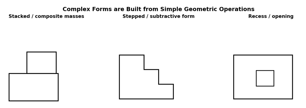
Operation | Construction idea |
Stacking | Construct lower block first; locate upper footprint on the top plane; raise the second height. |
Stepping | Divide the plan direction; transfer step heights on a true-height vertical; connect to the appropriate VP. |
Recess | Locate opening limits in plan and elevation; send the recess depth towards the opposite VP. |
Projection | Establish the projecting footprint in plan before raising or lowering its edges. |
Subtraction / L-shape | Project every plan corner; reconstruct the outline by alternating VP₁ and VP₂ directions. |
Exercise-book Exercise 06 (square pyramid) and Exercise 07 (three-step model) are useful source problems for this stage. Their inclined base orientations produce the two-directional recession characteristic of Unit III.
3.7 Curved Surfaces in Two-Point Perspective
A circle viewed in perspective generally appears as an ellipse. Directly sketching the ellipse by eye is unreliable when geometric accuracy is required. A common method is to first enclose the circle within a square, construct that square in perspective, transfer key points and then draw the smooth perspective ellipse through them.
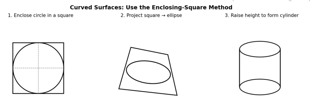
- 1. Draw the circle in plan inside a square of side equal to the circle diameter.
- 2. Mark side midpoints and, where greater accuracy is required, additional diagonal points.
- 3. Construct the square in two-point perspective on the required plane.
- 4. Transfer the circle points into the perspective quadrilateral.
- 5. Draw a smooth ellipse through the transferred points.
- 6. For a vertical cylinder, raise the required height, construct the second ellipse and join the visible vertical tangents.
Graphic Caution |
3.8 Furniture and Architectural Elements as an Intermediate Exercise
Although Unit III emphasises blocks, curved surfaces and residences, a table or simple pavilion is a useful bridge between pure geometric solids and architecture. It forces students to repeat the same two vanishing directions across several small elements while keeping vertical supports aligned.
- Start with an overall bounding box.
- Locate repeated legs/columns in plan.
- Project all horizontal edges towards the correct VP.
- Transfer heights from common level lines rather than estimating each element independently.
3.9 Two-Point Perspective of Architectural Forms
At architectural scale, the same geometric rules remain unchanged. The main difference is the number of secondary features: openings, porch projections, parapets, roof slabs, columns and level changes. These should be added only after the main building mass is correct.
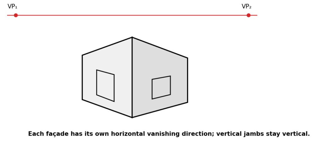
- 1. Construct the main building block from the plan and true height.
- 2. Locate doors and windows in plan; project their vertical limits into the perspective field.
- 3. Transfer sill, lintel and parapet heights from suitable reference verticals.
- 4. Use VP₁ for all edges parallel to the first façade direction and VP₂ for the second façade direction.
- 5. Construct canopies, projections or recesses from their plan footprints rather than by visual approximation.
- 6. Add rendering only after all construction geometry is verified.
Exercise-book Exercise 08, a shed with its long horizontal edges inclined at 45° to PP, is an appropriate transition from blocks to a complete architectural form.
3.10 Perspective of Residences
A residence combines nearly all Unit-III skills: multiple masses, openings, porch projections, parapets or roofs, steps, human scale and landscape elements. The correct approach is hierarchical: solve the main mass first, then secondary architectural features, then presentation details.
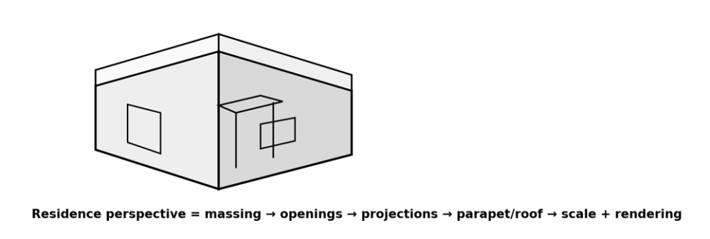
Stage | Priority |
1. Main massing | Overall plan, corner position, VPs, storey height |
2. Secondary masses | Porch, bay, stair, balcony, projections |
3. Openings | Door/window locations, sill and lintel levels |
4. Roof / parapet | Complete roof edges or parapet lines to correct VP |
5. Scale & context | Human figures, vegetation, paving, furniture/vehicles as needed |
6. Graphic finish | Line hierarchy, material tone, shadows and sciography |
3.11 Rendering and Graphic Presentation
Graphic element | Recommended treatment |
Nearest visible edges | Heavier line weight |
Secondary building edges | Medium line weight |
Construction / projection lines | Very light and removable |
Distant edges / background | Light line or reduced contrast |
Curved surfaces | Smooth continuous contour; avoid faceted ellipse |
Shadows / sciography | Consistent light direction; use to reinforce volume, not hide errors |
3.12 Common Errors in Two-Point Perspective
Common error | Correction |
Using the wrong VP for an edge | Classify every horizontal edge by its spatial direction before drawing it. |
Measuring depth directly on receding lines | Use plan visual rays, measuring methods or perspective subdivisions. |
Placing VP₁ and VP₂ arbitrarily | Derive them from SP using lines parallel to the two plan directions. |
Tilting verticals | Vertical edges remain vertical in standard two-point perspective. |
Constructing openings before the main mass | Complete the main block first, then locate secondary features. |
Drawing circles as casual ovals | Use an enclosing square and transferred points. |
Excessive distortion | Choose a reasonable SP and keep the object within a comfortable field of view. |
Over-dark construction lines | Use light guides; strengthen only the final object. |
3.13 Source Exercise-Book Problems Appropriate to Unit III
The following problems from the supplied exercise booklet are especially appropriate for Unit III because their principal horizontal directions are inclined to the Picture Plane and therefore generate two-directional recession.
Exercise | Problem focus |
Exercise 05 | Rectangular prism; 50 × 30 base, 55 high; longer edge 45° to PP. |
Exercise 06 | Square pyramid; base edges equally inclined to PP. |
Exercise 07 | Three-step model; longer edge 30° to PP. |
Exercise 08 | Shed; long horizontal edges 45° to PP; complete architectural form. |
3.14 Progressive Two-Point Perspective Problem Bank (01-12)
The following 12 problems are the progressive teaching set developed earlier for this course. They move from a basic prism to composite and curved forms and finally to architectural/residential applications. Where a viewer location was not originally specified, a practical Station Point / Central Plane value has been standardised here so that the exercise is directly usable in class.
Problem 01 – Rectangular Prism
|
Problem Statement |
Learning focus: Establish VP₁ and VP₂ and understand the basic two-directional convergence.
Problem 02 – Square Prism
|
Problem Statement |
Learning focus: Balanced 45°-45° orientation and symmetrical vanishing directions.
Problem 03 – Three-Step Composition
|
Problem Statement |
Learning focus: Repeated divisions, height transfer and stepped geometry.
Problem 04 – L-Shaped Solid
|
Problem Statement |
Learning focus: Project every corner of an irregular plan rather than guessing the final shape.
Problem 05 – Composite Blocks of Different Heights
|
Problem Statement |
Learning focus: Locate a secondary footprint on an upper perspective plane and transfer multiple heights.
Problem 06 – Block with Recessed Opening
|
Problem Statement |
Learning focus: Openings, recess depth and transfer of vertical levels.
Problem 07 – Block with Cylindrical Element
|
Problem Statement |
Learning focus: Curved surfaces, perspective ellipse and cylinder construction.
Problem 08 – Simple Furniture – Table
|
Problem Statement |
Learning focus: Repeated vertical elements and bounding-box construction.
Problem 09 – Architectural Pavilion
|
Problem Statement |
Learning focus: Columns, roof projection, repeated supports and architectural scale.
Problem 10 – Single-Storey Building with Openings
|
Problem Statement |
Learning focus: Façade openings, sill/lintel levels and parapet construction.
Problem 11 – Residence with Entrance Porch
|
Problem Statement |
Learning focus: Residential massing, porch projection and façade articulation.
Problem 12 – Integrated Architectural Composition
|
Problem Statement |
Learning focus: Design synthesis: combine all Unit-III skills in one controlled perspective composition.
3.15 Quick Revision
|
Two-Point Perspective at a Glance |
Review Questions
- 1. Define two-point perspective and explain when it is preferred over one-point perspective.
- 2. Describe the plan method used to obtain VP₁ and VP₂ from the Station Point.
- 3. Why should receding dimensions not be measured directly on the perspective lines?
- 4. Explain the construction sequence for a rectangular prism with one vertical edge touching PP.
- 5. Describe how a stepped or L-shaped block should be constructed in two-point perspective.
- 6. Explain the enclosing-square method for a circle or cylinder in perspective.
- 7. How are doors and windows accurately positioned on two visible building façades?
- 8. Describe the correct construction hierarchy for a residential two-point perspective.
Short MCQ Revision
|
Question |
Answer |
|
How many principal horizontal vanishing points are normally used? |
Two |
|
Where are horizontal VP₁ and VP₂ located? |
On the Horizon Line |
|
What happens to verticals in standard two-point perspective? |
They remain vertical |
|
How is VP₁ derived? |
Through SP draw a line parallel to Direction 1; project its PP intersection to HL |
|
How should a circle be constructed accurately? |
By projecting an enclosing square and transferring points |
|
What should be solved first in a residence? |
The main building mass / bounding geometry |
Suggested Submission / Practice Sheet Sequence
|
Sheet |
Problem(s) |
Purpose |
|
1 |
Problems 01-02 |
Simple prism fundamentals and two VPs |
|
2 |
Problems 03-04 |
Steps and irregular plan |
|
3 |
Problems 05-06 |
Composite block and recess |
|
4 |
Problem 07 |
Curved surface / cylinder |
|
5 |
Problem 08 |
Furniture / repeated verticals |
|
6 |
Problems 09-10 |
Pavilion and small building |
|
7 |
Problem 11 |
Residential perspective |
|
8 |
Problem 12 |
Integrated architectural composition |
End of Unit III
How useful was this post?
Click on a star to rate it!
Average rating 0 / 5. Vote count: 0
No votes so far! Be the first to rate this post.


