
AR402 | BUILDING CONSTRUCTION & MATERIALS–VII

CHAPTER 1: MODULAR COORDINATION
B.Arch. Fourth Year | Seventh Semester | Academic Session 2026–2027 | Unit I | 16 Contact Hours
Prescribed syllabus: Aims, basis, planning, dimensioning, assembly of components, tolerances, modules, referencing system, grids, positioning of functional elements: slabs, walls, staircases, tiles, etc.
1.1 Introduction and meaning
Modular coordination is a dimensional system that relates the size and location of building elements to a common unit known as a module. It enables independently designed or manufactured components to fit together with predictable joints and clearances. It connects architectural planning, manufacturing, setting-out and site assembly.
Historically, proportional systems and repeated units were used in traditional building. Industrialised production and prefabrication increased the need for common dimensional rules. Contemporary modular coordination also supports digital modelling and off-site fabrication.
1.2 Aims and objectives
. Establish dimensional compatibility between building components and assemblies.
- . Reduce unnecessary cutting, rework and material waste.
- . Facilitate standardisation, interchangeability and prefabrication.
- . Improve coordination of architecture, structure, services and finishes.
- . Simplify procurement, manufacturing, construction sequencing and quality control.
- . Maintain functional flexibility while using repeatable dimensional relationships.
Illustration: a 3,600 mm wall can be planned as six 600 mm coordinating units; the final component sizes must still incorporate the selected joints.
1.3 Basis: modules, multimodules and submodules
In metric modular coordination, the basic module is M = 100 mm. A multimodule is an integer multiple of M, such as 3M = 300 mm, 6M = 600 mm or 12M = 1,200 mm. Submodules are subdivisions such as M/2 = 50 mm or M/10 = 10 mm, used where finer coordination is required. The preferred sizes should follow the applicable standard.
Term | Example | Purpose |
Basic module | 1M = 100 mm | Common reference unit |
Multimodule | 12M = 1,200 mm | Panel and planning dimensions |
Submodule | M/10 = 10 mm | Fine dimensional coordination |
1.4 Modular planning
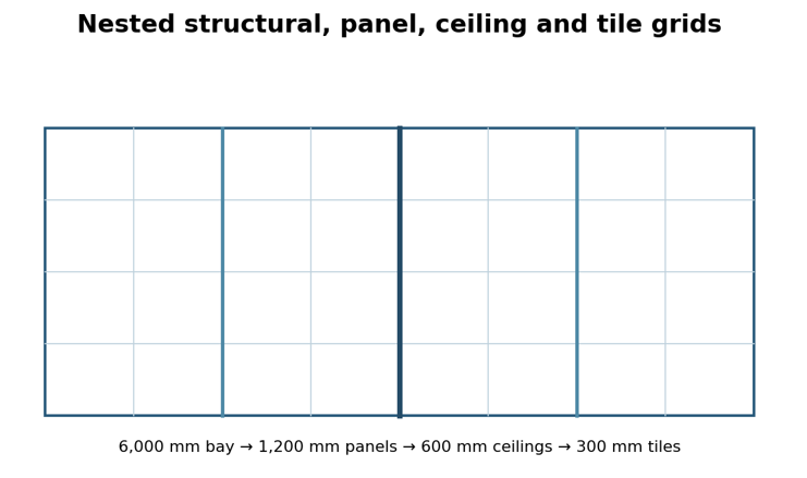
Modular planning organises structural grids, walls, openings, corridors, floor finishes and service zones through a common reference system. The designer selects appropriate increments for each scale: e.g., 6,000 mm structural bays, 1,200 mm panel increments, 600 mm ceiling grids and 300 mm tile increments.
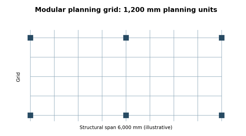
A planning grid is a design and setting-out tool; it does not replace structural sizing or code-based space standards. Structural spans should be selected using structural and functional requirements.
1.5 Dimensioning: coordinating, work and actual sizes
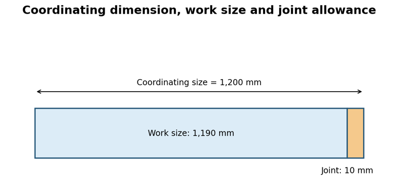
Coordinating size is the space allocated to a component within the dimensional system. Work size is its specified manufactured dimension. Actual size is the dimension measured after manufacture. A joint or clearance allowance may account for the difference between coordinating and work sizes.
Simplified example: coordinating width C = 1,200 mm, allocated joint allowance J = 10 mm; work width W = C − J = 1,190 mm. The equation depends on how the joint is allocated between adjoining components.
1.6 Assembly of building components
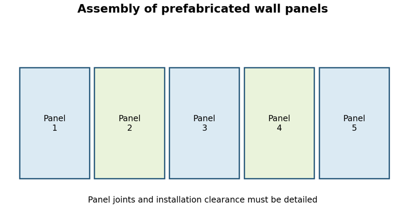
Assembly involves placing and connecting building components to form walls, floors, façades or complete modules. Design must consider dimensional compatibility, connections, bearing, access for installation, waterproofing, movement and construction sequence.
Principal assembly arrangements
- . Horizontal assembly: floor slabs, roof panels, suspended ceiling systems and floor finishes.
- . Vertical assembly: partition panels, cladding and precast walls.
- . Three-dimensional assembly: prefabricated room pods and volumetric modules.
1.7 Tolerances
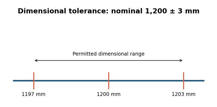
Tolerance is the permitted departure from a specified dimension or position. Manufacturing tolerances describe variations in product dimensions; construction and erection tolerances relate to setting-out and installation. Joint allowances should accommodate expected deviations, thermal movement and other relevant effects.
Example: 1,200 ± 3 mm permits an actual width between 1,197 and 1,203 mm. This is an instructional example rather than a universal permitted tolerance.
1.8 Referencing system
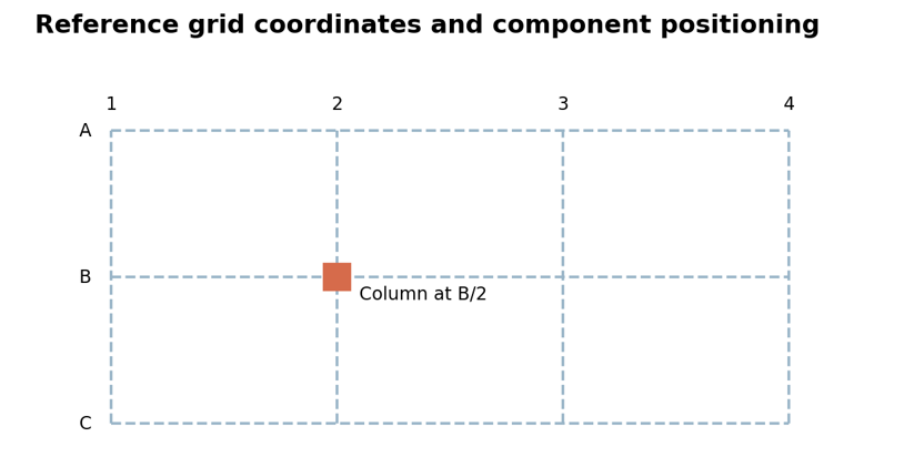
Reference points, lines and planes locate components in a common coordinate system. Structural grid intersections are typically identified by letters and numbers. In three-dimensional models, elements can be located using x, y and z coordinates. The referencing arrangement must be consistent between architectural, structural and service drawings.
1.9 Modular grids
A basic modular grid uses the fundamental module; a multimodular grid uses larger increments. Structural, planning and installation grids may coexist, provided their relationships are coordinated. For example, 6,000 ÷ 1,200 = 5; 1,200 ÷ 600 = 2; and 600 ÷ 300 = 2.
1.10 Positioning functional elements
1.10.1 Slabs
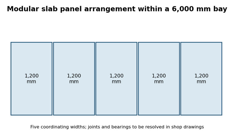
Slab layouts should coordinate structural supports, panel widths, bearing lengths, openings, joint details and erection sequence. For a 6,000 mm coordinating bay and a 1,200 mm panel module, five coordinating widths fit across the bay. Actual precast units must be dimensioned with bearings and joints considered.
1.10.2 Walls
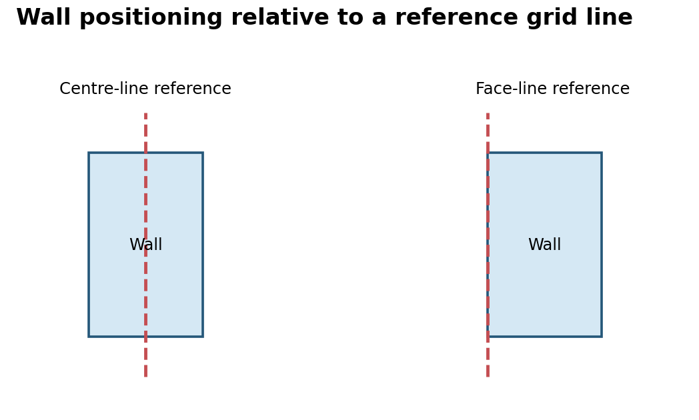
Walls can be referenced by their centre lines or by a selected face. For a 200 mm wall positioned on its centre line, the wall extends 100 mm either side of the line. Face-line positioning aligns a chosen wall face to a reference plane, useful for controlling clear internal dimensions.
1.10.3 Staircases
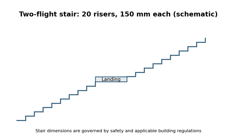
Modular coordination can organise stairwell widths, prefabricated flights, landings and interfaces with slabs. Stair geometry must first satisfy ergonomic, accessibility and fire-safety requirements. For a 3,000 mm floor-to-floor height and 150 mm risers, 3,000/150 = 20 risers. Two flights may each contain 10 risers. With 300 mm treads, a typical flight with 10 risers and an upper landing has 9 separate treads: horizontal run = 9 × 300 = 2,700 mm, excluding the landing.
1.10.4 Floor and wall tiles
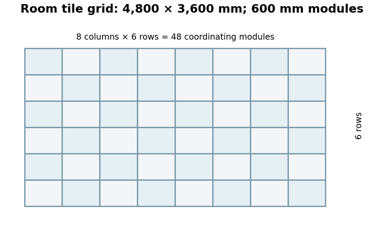
Tile planning should consider the tile work size, grout joint, room geometry, symmetry, movement joints and edge cuts. For a 4,800 × 3,600 mm room on a 600 mm coordinating grid, there are 8 × 6 = 48 modular units. This is not automatically the purchase quantity: cutting losses, breakage and actual joint dimensions must be added.
1.11 Modular coordination in prefabrication
Off-site manufactured precast slabs, cladding panels, partitions, bathroom pods and modular rooms benefit from agreed coordinating dimensions. Early agreement on interfaces, tolerance zones and lifting/transport constraints is essential. Repeatability can improve productivity but does not remove the need for detailed connections and quality checks.
1.12 Modular coordination and BIM
Building Information Modelling can encode grids, reference levels, standard component families, dimensional constraints and quantities. BIM supports interdisciplinary coordination and clash review, but model accuracy does not by itself guarantee dimensional accuracy on site.
1.13 Advantages and limitations
|
Advantages |
Limitations |
|
Component compatibility and repeatability |
May constrain unusual geometries |
|
Reduced cutting and rework |
Requires early interdisciplinary agreement |
|
Supports prefabrication |
Supplier dimensions may vary |
|
Clearer setting-out and quality control |
Tolerances and joints still need detailing |
|
Potential savings in time and waste |
Benefits depend on project scale and repetition |
1.14 Architectural design applications
At concept stage, modular grids guide space planning; at developed design, they coordinate columns, partitions and façade units; at detailing stage, they establish work sizes, joints and tolerances; during construction, they support setting-out, procurement and installation. Architects should evaluate modularity alongside spatial quality, accessibility, structural performance and climate-responsive design.
1.15 Worked numerical problems
Problem 1: module conversion
Solution: 1,800 mm ÷ 100 mm = 18M.
Problem 2: wall panels
Solution: 7,200 mm ÷ 1,200 mm = 6 coordinating panel widths.
Problem 3: work dimension
Solution: C = 1,500 mm and J = 10 mm: W = 1,500 − 10 = 1,490 mm.
Problem 4: tile grid
Solution: Room 4,800 × 3,600 mm, module 600 mm: (4,800/600) × (3,600/600) = 8 × 6 = 48 units.
Problem 5: risers
Solution: Floor height 3,300 mm; riser 150 mm: 3,300/150 = 22 risers.
1.16 Tutorials and practical exercises
Exercise 1: Modular planning grid
Prepare an A3 institutional-building plan using M = 100 mm; show grid, columns, walls and coordinated room dimensions.
Exercise 2: Wall panel system
Develop a 7,200 mm wall elevation with panel widths, joint details and work/coordinating dimensions.
Exercise 3: Tile setting-out
Prepare a dimensioned 4,800 × 3,600 mm room tile layout on a 600 mm coordinating grid, showing joints and edge conditions.
1.17 Examination-oriented questions
Short answers (2.5 marks each)
- 1. Define modular coordination and state two objectives.
- 2. Differentiate basic module, multimodule and submodule.
- 3. Distinguish coordinating size from work size.
- 4. Define manufacturing and erection tolerances.
- 5. What is a reference grid?
- 6. Explain centre-line wall positioning.
- 7. State two prefabrication applications.
- 8. Why is joint allowance necessary?
Descriptive questions (5 marks each)
- 9. Explain the aims, principles and architectural relevance of modular coordination.
- 10. Discuss modular dimensioning, joint allowance and tolerances with diagrams.
- 11. Describe referencing systems and structural/planning/installation grids.
- 12. Explain modular positioning of slabs and walls with sketches.
- 13. Demonstrate staircase and tile layout coordination with numerical examples.
- 14. Assess the benefits and limitations of modular coordination in prefabrication.
1.18 Suggested teaching schedule (16 hours)
|
Session |
Topic |
Hours |
|
1 |
Introduction, history, aims and objectives |
2 |
|
2 |
Basic module, multimodules and submodules |
2 |
|
3 |
Modular planning and dimensioning |
2 |
|
4 |
Component assembly and tolerances |
2 |
|
5 |
Referencing systems and modular grids |
2 |
|
6 |
Slabs and walls |
2 |
|
7 |
Staircases and tiles |
2 |
|
8 |
Prefabrication, numericals and tutorial |
2 |
|
|
Total |
16 |
1.19 Learning outcomes
- . Explain the purposes and fundamental principles of modular coordination.
- . Identify and calculate basic modular and multimodular dimensions.
- . Distinguish coordinating, work and actual sizes and explain tolerances.
- . Prepare and interpret modular grids and reference systems.
- . Apply modular planning to slabs, walls, stairs and tiles.
- . Evaluate modular coordination in prefabrication and digital design workflows.
1.20 Recommended references
- . ISO 1006 — Building construction: Modular coordination — Basic module.
- . ISO 2848 — Building construction: Modular coordination — Principles and rules.
- . ISO 1040 — Building construction: Modular coordination — Multimodules for horizontal coordinating dimensions.
- . IS 7922 — Recommendations for modular coordination in building industry (verify applicable edition).
- . Chudley, R., & Greeno, R. Building Construction Handbook.
- . Barry, R. The Construction of Buildings.
Chapter summary
Modular coordination provides a common dimensional language for planning, manufacturing and assembling building components. Effective use depends not only on selecting module-based dimensions but also on correct referencing, work-size calculations, tolerances, joints and interdisciplinary coordination. For architectural practice, it is a means to improve construction compatibility without compromising functional or regulatory requirements.
How useful was this post?
Click on a star to rate it!
Average rating 0 / 5. Vote count: 0
No votes so far! Be the first to rate this post.


