
UNIT 4: | AR203 | INTRODUCTION TO THREE-POINT PERSPECTIVE

4.1.1 Introduction to Three-Point Perspective
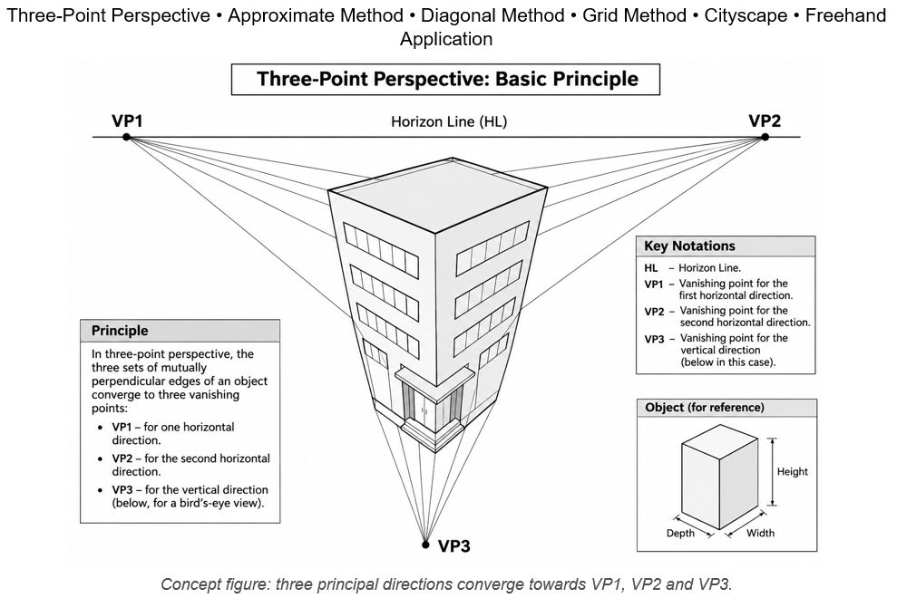
Three-point perspective is a perspective system in which the three principal sets of mutually perpendicular edges of an object converge towards three separate Vanishing Points. Two vanishing points represent the two principal horizontal directions of the object, while the third vanishing point represents the vertical direction.
In one-point and two-point perspective, the observer normally looks approximately horizontally towards the object. Consequently, vertical edges remain vertical. In three-point perspective, the observer looks either downward from an elevated position or upward from a lower position. Because the viewing direction is tilted, the vertical edges are no longer represented as parallel vertical lines; they also appear to converge.
This system is particularly useful for tall buildings, towers, high-rise developments, aerial architectural views, dramatic low-angle views, cityscapes and urban compositions. It communicates height and depth more strongly than a conventional two-point view.
Core Rule |
Three principal directions → three vanishing points. VP1 and VP2 control the two horizontal directions; VP3 controls the vertical direction. |
4.1.2 Basic Principle and the Three Vanishing Points
A rectangular building contains three principal families of parallel edges. In a three-point perspective, each family is represented by a separate vanishing system.
Direction in the actual object | Behaviour in three-point perspective |
Horizontal edges in first direction | Converge towards VP1 |
Horizontal edges in second direction | Converge towards VP2 |
Vertical edges | Converge towards VP3 |
VP1 and VP2 are normally located on the Horizon Line. VP3 lies away from the Horizon Line. Its position changes according to the direction in which the observer looks: below the object for a Bird’s-Eye view and above the object for a Worm’s-Eye view.
4.1.3 Why Do Vertical Lines Converge?
In standard two-point perspective, the viewing direction is approximately horizontal; therefore, the vertical direction remains parallel to the Picture Plane and vertical edges remain vertical in the drawing. When the observer tilts the viewing direction downward or upward, the vertical direction is no longer parallel to the Picture Plane. The vertical edges therefore recede relative to the observer and appear to converge towards a third Vanishing Point.
Memory Link |
Two-point perspective = horizontal viewing direction. Three-point perspective = upward or downward viewing direction. |
4.1.4 Principal Elements
Element | Function |
Horizon Line (HL) | Represents the observer’s horizontal eye direction; VP1 and VP2 normally lie on it. |
VP1 | Controls one family of horizontal receding edges. |
VP2 | Controls the second family of horizontal receding edges. |
VP3 | Controls the vertical direction; positioned above or below the object. |
Reference / nearest corner | Starting point from which width, depth and height are developed. |
4.1.5 Bird’s-Eye View and Worm’s-Eye View
The two principal forms of three-point perspective are defined by the observer’s position relative to the object. A Bird’s-Eye View represents the object from above while looking downward. A Worm’s-Eye View represents the object from below while looking upward.
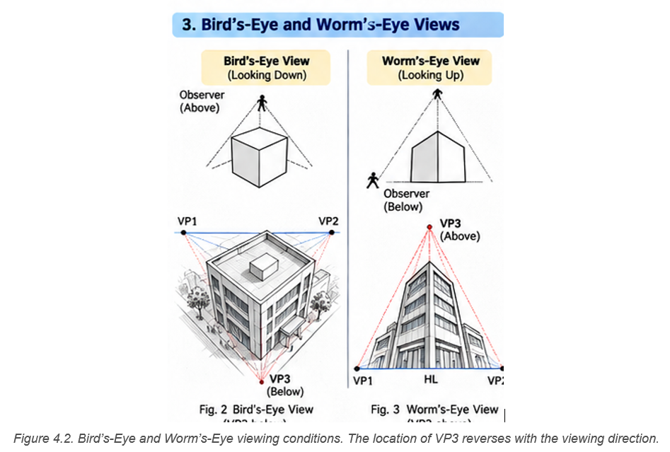
Characteristic | Bird’s-Eye View | Worm’s-Eye View |
Observer | Above the object | Below / near the base of the object |
Viewing direction | Downward | Upward |
VP3 | Below the object | Above the object |
Dominant visible surfaces | Roofs and upper surfaces | Façades and undersides |
Visual effect | Overview and spatial organisation | Height and monumentality |
Typical application | Campuses, complexes, urban overview | Towers, monuments, high-rises |
Simple Memory Rule |
Looking down → VP3 down. Looking up → VP3 up. |
4.1.6 Effect of the Position of VP3
The position of VP3 controls the intensity of vertical convergence. When VP3 is far from the building, vertical edges converge only slightly and the image approaches the appearance of two-point perspective. As VP3 moves closer, the vertical convergence becomes stronger and the view becomes more dramatic.
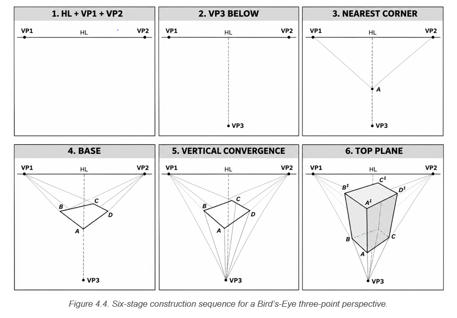
Step 1 – Draw the Horizon Line: Draw HL towards the upper portion of the sheet so that adequate space remains below for the building and VP3.
Step 2 – Locate VP1 and VP2: Place VP1 on the left and VP2 on the right of HL. Keep them reasonably far apart to avoid excessive horizontal distortion.
Step 3 – Locate VP3: Place VP3 below the proposed building. This is the defining condition of the Bird’s-Eye view.
Step 4 – Establish the nearest corner: Mark point A as the nearest lower corner. Draw one ray from A to VP1, one to VP2 and one to VP3.
Step 5 – Construct the base: Select B on A–VP1 and D on A–VP2. From B draw towards VP2 and from D towards VP1. Their intersection gives C; A–B–C–D forms the perspective base.
Step 6 – Draw vertical-converging edges: From A, B, C and D draw lines towards VP3. These represent the building’s vertical edges and must not remain parallel.
Step 7 – Establish the height: Select A¹ along the A–VP3 line to define the upper level of the nearest corner.
Step 8 – Develop upper corners: From A¹ draw towards VP1 and VP2 to intersect the vertical-converging lines through B and D, obtaining B¹ and D¹.
Step 9 – Complete the upper plane: From B¹ draw towards VP2 and from D¹ towards VP1 to obtain C¹. The top plane is now established and should be clearly visible from above.
Step 10 – Add architectural details: Construct parapets, windows, terraces, balconies and projections using the same three vanishing systems.
Step 11 – Finalise: Retain light construction lines, strengthen final visible edges, and add tone only after the geometry has been checked.
Memory Sequence |
HL → VP1 + VP2 → VP3 BELOW → nearest corner → base → vertical convergence → height → top plane → details |
Visual Characteristics of a Bird’s-Eye View
A successful Bird’s-Eye view must communicate the feeling that the observer is located above the architecture. Roofs and upper horizontal surfaces therefore become visually important. A stronger downward viewing angle reveals more roof surface, while a moderate elevated angle gives a subtler effect. The view should not merely resemble a normal two-point perspective with a roof added; the downward convergence of the verticals must remain evident.
4.1.8 Worm’s-Eye View: Step-by-Step Construction
A Worm’s-Eye View represents an object from a low position while the observer looks upward. It produces a strong impression of height, monumentality and vertical dominance. It is particularly useful for towers, high-rise buildings, monuments, entrance canopies and dramatic architectural visualisations.
Worked Example 2 – Tall Building Viewed from Below
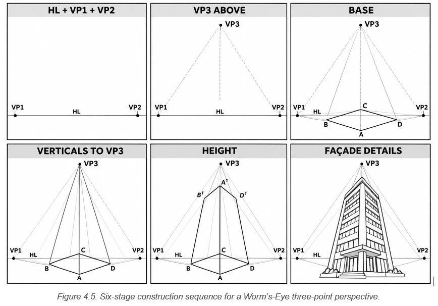
Step 1 – Establish the Horizon Line: Draw HL relatively low in the composition. This reinforces the feeling that the observer is positioned close to ground level.
Step 2 – Locate VP1 and VP2: Place VP1 and VP2 on HL, sufficiently far apart for a natural architectural view.
Step 3 – Locate VP3: Place VP3 above the building. This is the defining condition of a Worm’s-Eye perspective.
Step 4 – Establish the nearest lower corner: Mark A and draw the two horizontal receding directions towards VP1 and VP2, together with the vertical direction towards VP3.
Step 5 – Construct the footprint: Select B and D along the base directions, then complete C by drawing B–VP2 and D–VP1.
Step 6 – Draw vertical-converging edges: From A, B, C and D draw towards VP3.
Step 7 – Establish height: Select A¹ on A–VP3. The upper portions of the tower become visually compressed as they approach VP3.
Step 8 – Develop upper corners: From A¹ draw towards VP1 and VP2 to obtain B¹ and D¹; complete C¹ with the corresponding receding directions.
Step 9 – Add façade divisions: Floor bands and window lines follow VP1 or VP2; vertical mullions, façade joints and corners follow VP3.
Step 10 – Add projections: Canopies and balconies may expose their undersides in a Worm’s-Eye view. Construct their bounding form before detailing.
Step 11 – Final presentation: Strengthen the silhouette and use stronger line weight at lower, nearer portions; reduce emphasis towards the upper distance.
Memory Sequence |
HL → VP1 + VP2 → VP3 ABOVE → base → verticals to VP3 → height → upper edges → façade → details |
4.1.9 Architectural Details in Three-Point Perspective
Once the principal building volume is established, every architectural detail must follow the same vanishing-point system. A window placed on one façade does not remain a true rectangle: its horizontal edges converge towards the VP controlling that façade, while its vertical sides converge towards VP3. The same rule applies to balconies, parapets, structural grids, façade panels and projections.
Common studio mistake |
Constructing the building correctly and then drawing doors or windows as ordinary rectangles breaks the perspective immediately. Details must inherit the vanishing logic of the surface on which they are placed. |
4.1.10 Repetition of Floors and Openings
High-rise buildings frequently contain repeated floors, windows and façade modules. Equal real dimensions do not appear as equal distances in perspective; their apparent spacing reduces with distance. Repeated floors should therefore be established by a perspective subdivision method rather than by directly measuring equal intervals on a receding edge. The Diagonal Method, studied later in Unit IV, is particularly useful for systematic repetition.
4.1.11 Three-Point Perspective of a Cityscape
A cityscape represents a group of buildings and urban elements rather than a single isolated object. Three-point perspective is particularly effective for cityscapes because it communicates variations in building height, depth of streets, urban density, skyline and landmark hierarchy within one view.
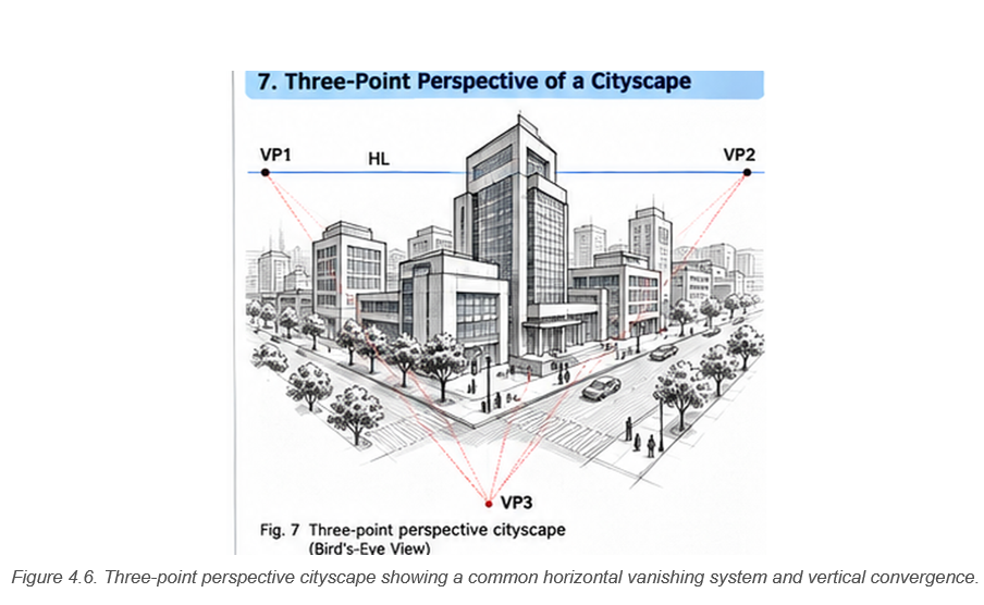
Worked Example 3 – Urban Composition of 4–5 Buildings
Step 1 – Determine the view: Decide whether the cityscape will use a Bird’s-Eye or Worm’s-Eye condition. A moderate Bird’s-Eye view is generally clearer for an urban overview.
Step 2 – Draw HL and establish VP1 and VP2: These two points establish the dominant street/building grid.
Step 3 – Locate VP3: For a Bird’s-Eye cityscape, place VP3 below the composition. Buildings aligned to the same grid share the same vanishing system.
Step 4 – Construct the dominant building: Begin with the principal or landmark building. Its mass establishes the main height and visual hierarchy.
Step 5 – Add secondary buildings: Vary their heights, widths, setbacks and distances. Avoid making all buildings identical.
Step 6 – Organise spatial layers: Establish foreground, middle ground and background so that the scene reads in depth.
Step 7 – Develop streets and open spaces: Road edges, pavements and setback lines should follow the appropriate horizontal vanishing direction.
Step 8 – Add façade articulation: Introduce selected floor bands, windows and projections only after the major masses are stable.
Step 9 – Add scale elements: Use a limited number of trees, people, vehicles, streetlights or street furniture.
Step 10 – Develop the skyline: Combine one dominant element with supporting buildings of different heights and roof profiles.
Step 11 – Apply line weight and tone: Use stronger lines and greater detail in the foreground; progressively simplify and lighten distant elements.
4.1.12 Foreground, Middle Ground and Background
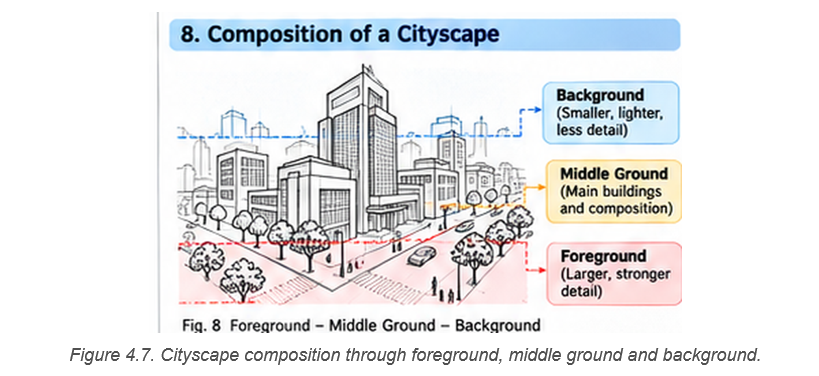
Foreground elements are closest to the observer and therefore appear larger, stronger and more detailed. The middle ground normally contains the principal architectural subject. Background buildings should be smaller, lighter and less detailed. This progressive reduction in size, contrast and detail strengthens spatial depth and prevents the cityscape from appearing flat.
4.1.13 Skyline and Architectural Hierarchy
A successful cityscape is not simply a collection of unrelated buildings. Visual hierarchy identifies the most important building or urban element. The dominant element may be emphasised through greater height, a stronger silhouette, a strategic position, a distinctive roof profile or contrast with surrounding forms. Secondary buildings should support rather than compete with the dominant element.
Cityscape Composition Rule |
One dominant element + supporting masses + varied heights/setbacks + clear spatial layers = stronger architectural hierarchy. |
4.1.14 Freehand Three-Point Perspective
Not every three-point perspective requires a fully instrumented construction. Architects frequently use freehand three-point perspective during concept development, design communication and urban sketching. The geometric principles remain unchanged even when the vanishing points lie outside the drawing sheet.
A useful freehand sequence is: establish the eye level; imagine VP1 and VP2; establish upward or downward vertical convergence; draw primary masses; add secondary masses; add openings; introduce context; then add tone and rendering. Freehand perspective should not be confused with random sketching: convincing freehand work depends on consistent convergence, believable proportions and spatial hierarchy.
Freehand Sequence |
Eye level → directional convergence → primary masses → secondary masses → openings → context → tone |
4.1.15 Comparison: One-, Two- and Three-Point Perspective
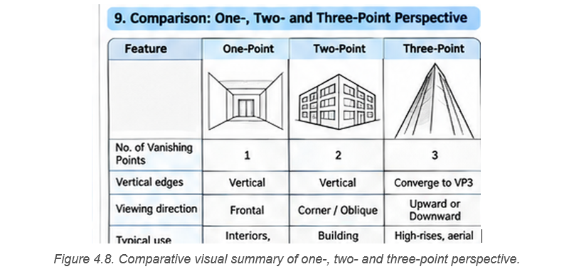
Feature | One-Point | Two-Point | Three-Point |
Principal vanishing points | 1 | 2 | 3 |
Vertical edges | Remain vertical | Remain vertical | Converge to VP3 |
Viewing direction | Frontal | Corner / oblique | Upward or downward |
Typical use | Interiors, corridors | Building exteriors | High-rises, aerial views, cityscapes |
Visual character | Controlled / frontal | Spatial / dynamic | Dramatic / height-oriented |
4.1.16 Common Errors and Corrections

Common error | Why it is incorrect | Correction |
Keeping vertical edges parallel | Produces a two-point rather than three-point effect | Direct all vertical edges towards VP3 |
Placing VP3 on HL | VP3 represents the vertical direction | Position VP3 above or below the object |
Using different vertical VPs | Parallel real-world verticals must share one VP | Use one common VP3 |
Drawing windows as rectangles | Openings must follow perspective convergence | Direct their edges to the relevant VPs |
VP1 and VP2 too close | Produces excessive horizontal distortion | Increase the distance between the horizontal VPs |
VP3 too close | Creates exaggerated vertical distortion | Position VP3 farther from the object |
Equal floor spacing drawn directly | Perspective intervals diminish with distance | Use a perspective subdivision method |
Detailing before the primary mass | Makes geometric errors difficult to correct | Construct the principal volume first |
All cityscape buildings equal | Produces weak skyline and hierarchy | Vary height, setback and dominance |
Background as strong as foreground | Reduces depth | Reduce line weight, contrast and detail with distance |
4.1.17 When Should Three-Point Perspective Be Used?
Three-point perspective is appropriate when the communication objective requires a strong sense of height, depth or elevated observation. Use a Bird’s-Eye view when the relationship between roofs, building masses, streets and urban open spaces is important. Use a Worm’s-Eye view when height, monumentality or the experience of looking upward is important. For ordinary residential exteriors viewed at approximately human eye level, two-point perspective is generally more appropriate because three-point convergence may introduce unnecessary distortion.
4.1.18 Alignment with Part III Exercise Book
Part III exercise | Concept practised |
Problem 01 – Bird’s-Eye View | VP3 below; elevated observer; visible upper surfaces |
Problem 02 – Worm’s-Eye View | VP3 above; low observer; strong vertical emphasis |
Problem 03 – Cityscape | Multiple building masses, skyline, hierarchy and urban depth |
Problems 04–06 of Part III then continue into the Approximate Method, Diagonal Method and Grid Method. These should be studied as separate perspective-construction techniques after students are comfortable with the fundamental one-, two- and three-point systems.
4.1.19 Quick Revision
- Three-point perspective uses VP1 and VP2 for the horizontal directions and VP3 for the vertical direction.
- Bird’s-Eye View: observer looks downward and VP3 lies below the building.
- Worm’s-Eye View: observer looks upward and VP3 lies above the building.
- A distant VP3 gives mild convergence; a closer VP3 gives a stronger dramatic effect.
- Architectural details must follow the same three vanishing systems as the primary mass.
- Cityscape representation combines correct perspective with foreground–middle ground–background, skyline variation and hierarchy.
Final Memory Rule |
BIRD’S-EYE → LOOK DOWN → VP3 DOWN |
Review Questions
- Define three-point perspective and explain why a third vanishing point is required.
- Differentiate between two-point and three-point perspective.
- Explain the position and function of VP1, VP2 and VP3.
- Why do vertical edges converge in three-point perspective?
- Explain the visual characteristics of a Bird’s-Eye View.
- Describe the construction of a rectangular building in Bird’s-Eye perspective.
- Explain the visual characteristics of a Worm’s-Eye View.
- How does the position of VP3 influence distortion?
- How should doors, windows and façade panels be constructed in three-point perspective?
- Describe the procedure for developing a three-point cityscape.
- Explain the role of foreground, middle ground and background.
- What is architectural hierarchy and how can it be expressed in a cityscape?
- Explain why freehand perspective is not the same as random sketching.
- State five common errors in three-point perspective and their corrections.
- Compare one-, two- and three-point perspective with suitable architectural applications.
4.2 Perspective by Approximate Method
The Approximate Method is a rapid method of preparing a perspective when the principal objective is to obtain a visually convincing architectural view without projecting every point through a complete measured plan-and-visual-ray construction. It is especially useful during conceptual design, studio discussions, jury drawings, quick exterior studies and freehand architectural presentation.
Although the method is faster, it is not arbitrary. The perspective still depends on a correct Horizon Line, consistent Vanishing Points, controlled proportions and a clear understanding of how architectural edges recede in space. The difference is that many dimensions and depths are judged proportionally instead of being transferred point-by-point from a measured plan.
Core idea |
4.2.1 When the Approximate Method is Appropriate
- Early design development, when the form is still changing and exact measured projection would be unnecessarily time-consuming.
- Quick exterior perspectives for explaining building mass, façade composition and entrance character.
- Freehand or semi-instrumental studio work where visual clarity is more important than exact dimensional transfer.
- Views in which the principal architectural geometry is regular and can be controlled through one- or two-point vanishing systems.
The method should not be treated as a substitute for rigorous construction when exact dimensional accuracy, documentation or verification of measured spatial relationships is required.
4.2.2 Construction Logic
Stage | Purpose |
Horizon Line (HL) | Establishes the observer’s eye level and controls the vertical position of the view. |
Vanishing Point(s) | Control the receding horizontal directions of the building. |
Primary Mass | Establishes overall width, depth and height before details are introduced. |
Secondary Masses | Porches, projections, recesses, parapets, steps and roof features are added to the main volume. |
Openings | Doors and windows are placed only after the principal planes are stable. |
Context and Rendering | Vegetation, people, paving, shade and shadow are added after the geometry has been checked. |
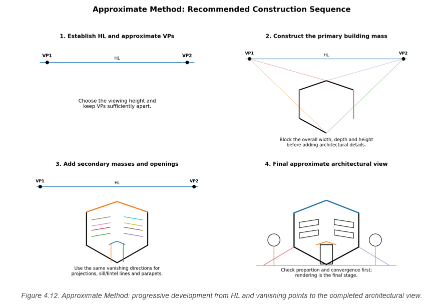
4.2.3 Worked Example – Simple Residential Exterior
Consider a simple single-storey residence to be represented in two-point perspective. The exact plan may be available, but the drawing is to be developed quickly for presentation rather than by projecting every plan corner.
- Decide the observer position and draw the Horizon Line at a height appropriate to the intended view. For a normal pedestrian view, keep the eye level close to the height of a standing person.
- Locate VP1 and VP2 sufficiently far apart. Extremely close vanishing points create exaggerated distortion and should be avoided for normal architectural representation.
- Draw the nearest vertical edge of the principal building mass. This edge becomes the primary proportion reference for the view.
- From the top and bottom of this vertical edge, draw receding lines towards VP1 and VP2. Visually estimate the required depth on each side and close the principal building mass.
- Establish major horizontal levels such as plinth, sill, lintel, slab and parapet. Each line must converge towards the vanishing point controlling that façade.
- Add the entrance porch, canopy, balcony, projection or recess as a secondary bounding box attached to the main volume. Do not begin with detailed mouldings or window frames.
- Place doors and windows proportionally. Use façade subdivision or diagonals where a repeated arrangement must be controlled more carefully.
- Add steps, paving, limited vegetation and human figures to communicate scale. These elements should support the architecture rather than hide construction errors.
- Check the entire view for inconsistent convergence, excessive depth and distorted proportions. Only then strengthen final edges and apply tone, texture or sciography.
Important |
4.2.4 Advantages and Limitations
Advantages | Limitations |
Fast and suitable for design exploration. | Does not provide the same dimensional control as a measured plan-based construction. |
Encourages visual judgement and architectural proportion. | Errors in the initial vanishing directions can propagate through the whole drawing. |
Useful for jury drawings and conceptual exterior views. | Not ideal where exact placement of irregular objects is required. |
Can be combined with freehand rendering. | Depends strongly on the student’s understanding of perspective fundamentals. |
4.2.5 Common Errors
Error | Correction |
Choosing VP1 and VP2 too close to the building | Move the vanishing points farther apart to reduce distortion. |
Estimating every feature independently | Construct the main mass and major levels first; derive details from them. |
Drawing façade openings as rectangles | Their horizontal edges must follow the vanishing direction of the façade. |
Rendering before checking geometry | Complete and verify construction before tone, texture and entourage. |
Changing eye level during the drawing | Keep one consistent Horizon Line for the entire view. |
4.3 Perspective by Diagonal Method
The Diagonal Method is a geometric perspective technique used to locate centres, divide receding rectangular planes and control repeated or proportional elements without measuring equal distances directly along a foreshortened line. It is particularly useful for paving, façade panels, windows, floor tiles, ceiling grids, columns, repetitive bays and other modular architectural elements.
Its fundamental principle is simple: the diagonals of a rectangle meet at its geometric centre. This property remains valid after the rectangle is seen in perspective. Therefore, crossing the diagonals of a perspective quadrilateral gives the perspective position of the true centre, even though that centre will not appear halfway across the shape on the sheet.
Core rule |
4.3.1 Locating the Centre of a Receding Plane
- Construct the required rectangular surface in perspective and label its corners A, B, C and D.
- Draw the two diagonals AC and BD.
- Their intersection O is the geometric centre of the original rectangle represented in perspective.
- Through O draw a line in the required principal direction. This centre-line divides the perspective plane into equal halves in the corresponding real-world direction.
- Repeat the same construction within each half when quarters or further even subdivisions are required.
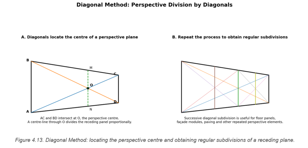
4.3.2 Subdividing a Receding Surface into Equal Parts
For an even number of subdivisions, repeated diagonal bisection is particularly convenient. For an odd number of equal parts, such as five façade bays, a measurable forward edge or temporary measuring line can be divided into the required number of equal parts and those proportions can then be transferred into the receding plane through the same vanishing system and diagonal construction. This prevents the common mistake of spacing the bays equally on the paper.
The apparent intervals become progressively smaller as they recede. The reduction is not arbitrary; it is a consequence of perspective projection. This is why direct scale measurement on a receding line should be avoided.
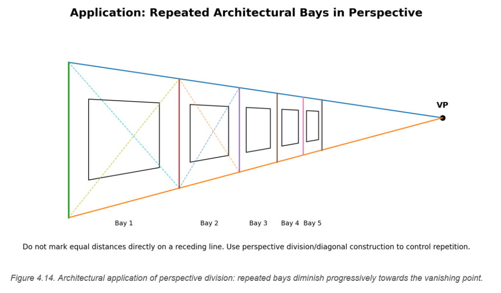
4.3.3 Worked Example – Five Repetitive Architectural Bays
Consider a colonnade or façade containing five equal bays receding away from the observer.
- Establish the Horizon Line and the Vanishing Point controlling the receding direction of the façade or corridor.
- Construct the top and bottom boundary lines of the façade plane. These lines converge towards the same Vanishing Point.
- Establish the first bay accurately near the observer. Its near dimensions act as the reference module.
- Where a forward edge parallel to the Picture Plane is available, use it as a measuring line and divide it into five equal parts. Project these divisions into the receding plane towards the appropriate Vanishing Point.
- Draw the principal diagonal of the receding rectangular plane. Intersections between this diagonal and the projected division lines determine the correct positions of the cross-lines in depth.
- Draw the successive verticals or cross-lines through the obtained points. The apparent bay widths will reduce progressively as they recede.
- Construct columns, window openings, beams or other repeated elements within each bay using the same perspective framework.
- Darken only the final visible edges after verifying that all repeated elements remain aligned with the same vanishing system.
4.3.4 Practical Architectural Uses
- Dividing a wall or façade into equal panels.
- Locating the centre of a door, window, wall panel or ceiling panel in perspective.
- Constructing repetitive structural or façade bays.
- Laying out floor tiles, paving modules or ceiling grids.
- Repeating columns, fence posts, streetlights or similar elements in depth.
- Providing a geometric check when visual spacing appears uncertain.
4.3.5 Common Errors
Error | Correction |
Marking equal bay widths directly along the receding edge | Use diagonal division and/or a measuring line; equal real distances do not appear equal on paper. |
Using diagonals before establishing the perspective quadrilateral | Construct the plane correctly first; diagonals only subdivide a valid perspective plane. |
Drawing cross-lines with inconsistent convergence | Every line belonging to the same spatial direction must share the same VP. |
Assuming the visual midpoint is the geometric midpoint | Find the true centre by crossing the diagonals. |
Accumulating small errors across many repeated bays | Prefer subdividing a larger known extent when possible, and check the pattern at intervals. |
4.4 Perspective by Grid Method
The Grid Method is a systematic technique for transferring the position of objects from a measured plan, sketch or reference layout into a perspective view. The source plan is divided into a regular network of cells, and a corresponding grid is constructed in perspective. Objects are then located cell-by-cell before their vertical heights are developed.
This method is especially useful when several objects have irregular positions that would be difficult to estimate visually. It is therefore well suited to interior layouts, furniture arrangements, exhibition spaces, streetscapes, landscape compositions and small site views.
Core rule |
4.4.1 Principle of the Grid Method
A regular square grid in plan does not remain a regular square grid in perspective. The lines receding in depth converge towards the appropriate Vanishing Point, and the spacing between successive cross-lines decreases with distance. Nevertheless, each perspective cell corresponds to a known cell in the source plan. This correspondence allows the draughtsperson to transfer complex positions systematically.
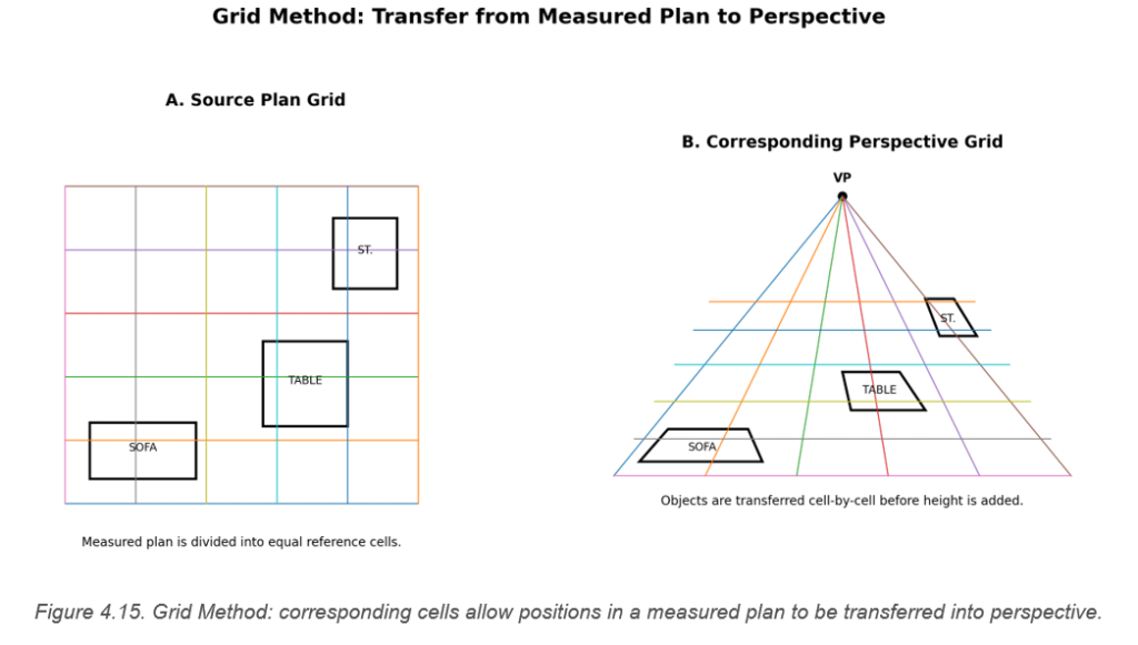
4.4.2 Construction of a Perspective Grid
- Prepare the source plan and overlay it with a regular square grid. Select a grid size that is small enough to locate important objects but not so small that the drawing becomes congested.
- Establish the Horizon Line and the required Vanishing Point or Vanishing Points for the intended perspective view.
- Construct the front boundary of the perspective grid. Where this boundary is parallel to the Picture Plane, its divisions can be set out directly as a measuring line.
- From the front grid divisions, draw receding lines towards the appropriate Vanishing Point.
- Establish the depth divisions by a suitable perspective subdivision technique, such as diagonals or a measuring point. Do not draw equal horizontal intervals by eye.
- Number or identify the cells in the source plan and the perspective grid if the layout is complex.
- Transfer the footprint of each architectural or furniture element by locating its corners within corresponding cells.
- After the footprints are correct, raise verticals and transfer the required heights using the perspective system of the view.
- Complete openings, furniture details and context only after the principal spatial locations have been checked.
4.4.3 Worked Example – Interior Space with Furniture
Consider a simple room containing a sofa, table and storage unit. The measured plan is divided into a regular grid before the perspective is developed.
- Mark the room boundaries, door/window positions and furniture footprints on the source grid.
- Construct the floor perspective grid using the selected eye level and Vanishing Point.
- Locate each furniture footprint by identifying the source cells containing its corners and transferring those positions to the corresponding perspective cells.
- Join the transferred points to obtain the perspective footprint of the sofa, table and storage unit.
- Raise verticals from the footprint corners and establish furniture heights from a suitable reference or proportional judgement.
- Construct the room walls, openings and ceiling only after the floor-grid relationships are stable.
- Check that furniture sits correctly on the floor plane and does not float, penetrate walls or change orientation accidentally.
- Remove or lighten unnecessary grid lines and strengthen the final architectural and furniture edges.
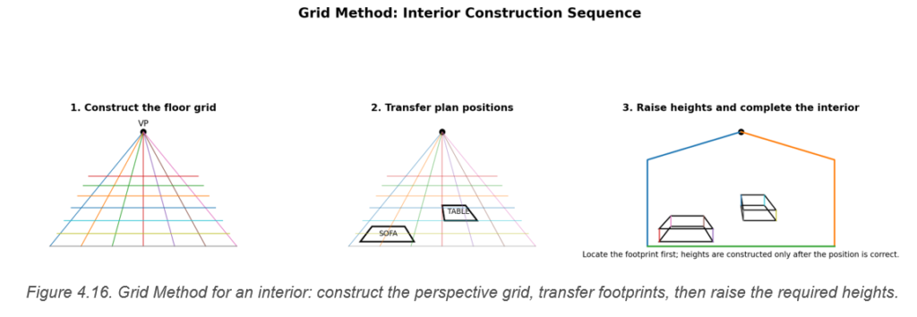
4.4.4 Choosing the Grid Size
A coarse grid is quicker but provides limited positional accuracy. A very fine grid improves location control but can make the drawing difficult to read. The grid size should therefore respond to the complexity of the subject. Large furniture and simple rooms may require only a moderate grid, whereas irregular layouts or several small objects benefit from a finer reference network.
4.4.5 Advantages and Limitations
Advantages | Limitations |
Systematic and easy to check cell-by-cell. | Initial grid construction requires time. |
Useful for irregularly placed furniture and site elements. | A poorly constructed grid transfers errors to every object. |
Reduces dependence on visual guessing. | Too many grid lines can make the drawing visually congested. |
Can be used for interiors, landscapes and streetscapes. | Object heights still require a separate height-transfer procedure. |
4.4.6 Common Errors
Error | Correction |
Using equal spacing for grid cross-lines in depth | Perspective depth divisions must diminish as they recede. |
Transferring an object to the wrong cell | Identify or number source and perspective cells before transferring complex layouts. |
Raising heights before checking the footprint | Complete plan-position transfer first, then construct vertical dimensions. |
Changing the object orientation during transfer | Follow the same grid axes and vanishing directions as the source layout. |
Keeping every grid line dark in the final drawing | Use the grid as construction; lighten or remove unnecessary guides before final presentation. |
4.5 Selecting the Appropriate Innovative Method
Method | Best suited for | Primary control | Typical AR203 application |
Approximate Method | Rapid design visualisation and concept presentation | Vanishing directions + visual proportion | Simple residential exterior |
Diagonal Method | Centres, subdivisions and repeated modules | Geometric diagonals + measuring/vanishing directions | Façade, colonnade, paving or repeated bays |
Grid Method | Systematic transfer of several plan positions | Corresponding source and perspective cells | Interior space with furniture |
These methods are complementary rather than competing. An architect may begin with an approximate perspective to explore a design, use diagonal construction to control façade repetition, and use a grid when several objects must be transferred from a measured plan. The appropriate method depends on the required accuracy, available time and complexity of the subject.
4.6 Alignment with Part III Exercise Book
Part III problem | Study-note section | Primary learning |
Problem 01 – Bird’s-Eye View | 4.1 | Three-point perspective with VP3 below |
Problem 02 – Worm’s-Eye View | 4.1 | Three-point perspective with VP3 above |
Problem 03 – Cityscape | 4.1 | Multiple masses, skyline, hierarchy and depth |
Problem 04 – Approximate Method | 4.2 | Rapid two-point residential exterior |
Problem 05 – Diagonal Method | 4.3 | Perspective subdivision and repeated architectural bays |
Problem 06 – Grid Method | 4.4 | Transfer of an interior/furniture layout from a measured grid |
4.7 Unit IV – Final Quick Revision
- Three-point perspective uses VP1 and VP2 for horizontal directions and VP3 for the vertical direction.
- Bird’s-Eye View: observer looks down and VP3 lies below the object.
- Worm’s-Eye View: observer looks up and VP3 lies above the object.
- Approximate Method: rapid perspective based on controlled vanishing directions and proportional judgement.
- Diagonal Method: geometric subdivision of receding planes; useful for centres, repeated modules and depth divisions.
- Grid Method: systematic transfer of plan positions through corresponding grid cells; locate footprints before raising heights.
- In every method, construction accuracy must be established before rendering, texture, entourage and sciography.
Final Review Questions – Innovative Methods
- Define the Approximate Method and state two situations in which it is appropriate.
- Describe the step-by-step procedure for preparing an approximate two-point perspective of a simple residence.
- Why must the Horizon Line and Vanishing Points remain consistent even in an approximate perspective?
- Explain the geometric principle on which the Diagonal Method is based.
- How can the true centre of a rectangular plane be located in perspective?
- Why should equal divisions not be measured directly along a receding line?
- Explain how the Diagonal Method can be applied to façade panels, paving or repeated bays.
- Define the Grid Method and explain why it is useful for interior layouts.
- Describe the procedure for transferring furniture from a measured plan grid to a perspective grid.
- Compare the Approximate, Diagonal and Grid Methods in terms of purpose, accuracy and architectural application.
How useful was this post?
Click on a star to rate it!
Average rating 0 / 5. Vote count: 0
No votes so far! Be the first to rate this post.


