
Unit I Introduction to Perspective

This unit builds the conceptual foundation required for one-point, two-point and three-point perspective construction. The emphasis is on understanding how an observer, an object and a projection plane together produce a perspective image.
| Core Learning Goals |
| Understand why perspective is used; distinguish perspective from metric projection; recognise visual depth principles; identify all elements of perspective anatomy; understand their relationships; distinguish one-, two- and three-point perspective; and select a suitable viewpoint for architectural representation. |
- 1. Meaning and Purpose of Perspective Drawing
- 2. Perspective and Human Visual Perception
- 3. 2D Technical Drawings and 3D Visual Representation
- 4. Perspective Projection and Metric Projection
- 5. Basic Visual Principles of Perspective
- 6. Anatomy / Elements of Perspective
- 7. Relationships Between Perspective Elements
- 8. Horizon Line and Eye Level
- 9. Station Point and Viewpoint
- 10. Picture Plane
- 11. Cone of Vision
- 12. Visual Rays
- 13. Vanishing Point and Measuring Point
- 14. Types of Perspective
- 15. Architectural Applications
- 16. Perspective as an Architectural Communication Tool
- 17. Quick Revision and Practice Questions
1. Meaning and Purpose of Perspective Drawing
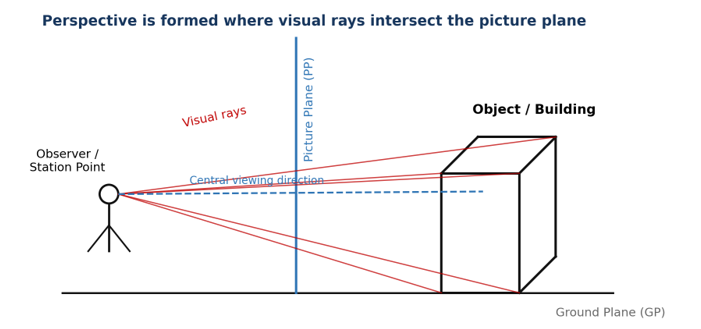
Perspective drawing is a method of representing a three-dimensional object or space on a two-dimensional surface so that it resembles the way the object is perceived from a particular viewpoint. It is therefore a view-dependent method of representation.
In architecture, perspective is used because plans, elevations and sections describe a building accurately, but they do not always communicate how that building or space may be experienced by a person. Perspective bridges this gap by showing depth, scale, spatial relationships and the visual character of a design.
| Core Idea |
| Object + Observer + Viewing Direction = Perspective View |
- Visualise a proposed building or space before construction.
- Evaluate massing, proportion, depth and spatial relationships.
- Communicate architectural ideas to clients, juries and non-technical viewers.
- Represent interior spaces, building exteriors, streetscapes and urban scenes in a visually understandable manner.
- Support design thinking by testing different viewpoints and compositions.
2. Perspective and Human Visual Perception
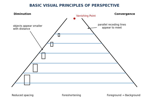
Perspective is based on the way objects appear to a viewer rather than on their actual measurable size. A nearby object appears larger than the same object placed farther away. Parallel edges, such as the sides of a road or corridor, appear to approach one another with distance.
Linear perspective converts these visual effects into a geometrical system based on a fixed observer position. Human vision is binocular and dynamic, so perspective should be understood as a geometrical approximation of visual perception from a selected viewpoint.
- Apparent size decreases with distance.
- Parallel receding edges appear to converge.
- Repeated spacing appears progressively compressed.
- Near objects may overlap distant objects.
- Detail and contrast generally reduce with distance.
3. 2D Technical Drawings and 3D Visual Representation
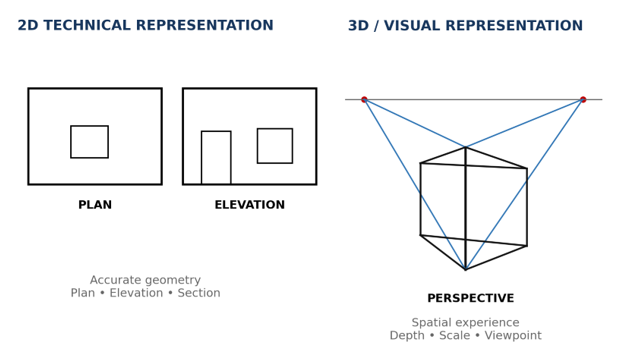
Architectural drawings communicate either technical information, spatial experience, or both. Plans, elevations and sections are precise two-dimensional descriptions. Perspective, isometric and axonometric drawings help the viewer understand three-dimensional form and spatial relationships.
Aspect | 2D Technical Drawings | 3D / Visual Representation |
Typical drawings | Plan, elevation, section | Perspective, isometric, axonometric |
Primary purpose | Dimensions, organisation, construction information | Form, depth, spatial experience |
View dependence | Generally not based on normal human viewpoint | Perspective is strongly viewpoint-dependent |
Parallel edges | Remain geometrically controlled | May visually converge in perspective |
Measurement | Directly measurable at stated scale | Perspective is primarily visual, not directly measurable |
Remember |
Plan explains organisation; elevation explains vertical composition; section explains internal relationships; perspective explains visual experience. |
4. Perspective Projection and Metric Projection
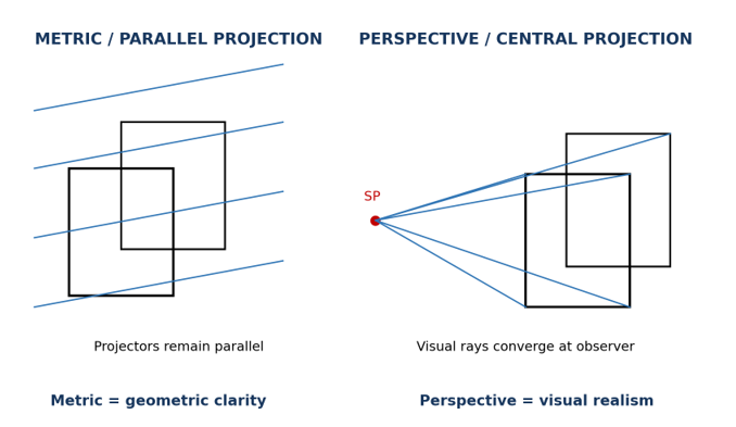
Projection is the transfer of points from an object to a drawing surface. In metric or parallel projection systems, the projectors remain parallel. In perspective projection, visual rays converge toward a finite observer or Station Point.
Feature | Perspective Projection | Metric / Parallel Projection |
Observer | Fixed finite viewpoint | No finite observer required |
Projectors | Converge toward observer | Remain parallel |
Distant objects | Appear smaller | Size controlled by projection system |
Parallel receding lines | May meet at vanishing point | Normally remain parallel |
Use | Visual realism and spatial communication | Geometric clarity and technical representation |
Key Distinction |
Metric projection represents geometry; perspective represents apparent visual geometry. |
5. Basic Visual Principles of Perspective
5.1 Diminution
Objects appear progressively smaller as their distance from the observer increases.
5.2 Convergence
Parallel lines receding in depth appear to approach one another and may visually meet at a vanishing point.
5.3 Foreshortening
A line or surface seen obliquely appears shorter than its actual dimension.
5.4 Overlapping
When one object partially hides another, the visible object is interpreted as being closer.
5.5 Relative Scale
People, doors, furniture, vehicles and other familiar objects help communicate architectural scale.
5.6 Reduction of Spacing
Equal intervals between columns, tiles or openings appear progressively smaller with distance.
5.7 Foreground, Middle Ground and Background
Organising a drawing into depth zones improves the perception of distance and spatial hierarchy.
5.8 Detail and Contrast
Distant elements are normally represented with less detail and reduced visual emphasis.
Depth Sequence |
Increasing distance → smaller apparent size → compressed spacing → reduced detail → stronger sense of depth. |
6. Anatomy / Elements of Perspective
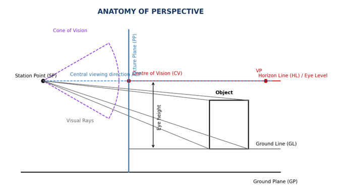
Perspective construction is based on a small set of reference elements. These terms should be understood before attempting graphical construction.
Element | Abbreviation | Meaning / Function |
Observer | — | Person viewing the object or space. |
Station Point | SP | Exact position of the observer in plan. |
Picture Plane | PP | Imaginary transparent vertical plane on which the perspective image is formed. |
Ground Plane | GP | Horizontal plane on which the object and observer are assumed to stand. |
Ground Line | GL | Intersection of the Picture Plane and Ground Plane. |
Eye Level | EL | Height of the observer’s eye above GP. |
Horizon Line | HL | Horizontal line on PP corresponding to eye level. |
Central Plane | CP | Vertical plane through SP, normally perpendicular to PP, defining the central viewing direction. |
Centre of Vision | CV | Point where the central viewing direction meets PP. |
Visual Ray | — | Imaginary line joining SP to a point on the object. |
Cone of Vision | — | Comfortable viewing region within which distortion is limited. |
Vanishing Point | VP | Point toward which a family of parallel receding lines appears to converge. |
Measuring Point | MP | Construction point used in some perspective methods to transfer true dimensions onto receding lines. |
7. Relationships Between Perspective Elements
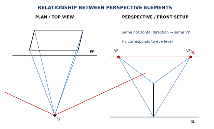
The elements of perspective work as one connected projection system. Changing one of them can change the resulting view.
- PP ∩ GP = GL.
- HL represents the observer’s eye level on the picture plane.
- CP passes through SP and defines the central viewing direction.
- CV is the point where the central viewing direction meets PP.
- A visual ray joins SP to an object point; its intersection with PP helps locate the corresponding perspective point.
- Horizontal lines having the same spatial direction share the same vanishing point.
Most Important Rule |
Same family of parallel spatial lines → same vanishing point. |
8. Horizon Line and Eye Level
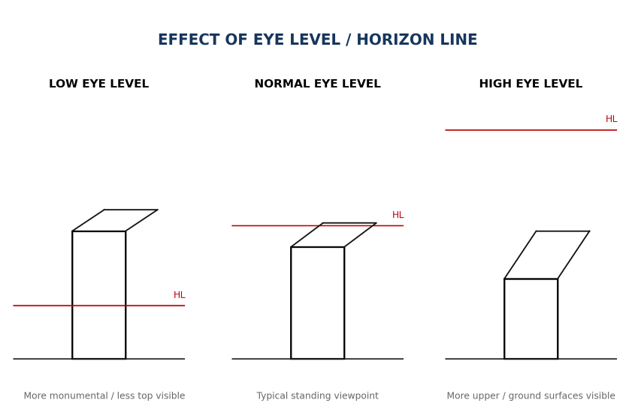
The Horizon Line is the horizontal line on the Picture Plane corresponding to the observer’s eye level. It is one of the strongest indicators of viewpoint in a perspective drawing.
- If a horizontal surface lies below the eye level, its top may be visible.
- A surface close to eye level may appear nearly edge-on.
- A surface above eye level may reveal its underside.
- Raising or lowering the eye level changes the amount of upper and lower surfaces visible in the scene.
- A low viewpoint can make a building appear more monumental; a high viewpoint can reveal more ground or roof surfaces.
Important |
A high or low eye level alone does not automatically create three-point perspective. Vertical convergence occurs when the viewing direction is tilted upward or downward. |
9. Station Point and Viewpoint
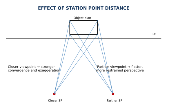
The Station Point identifies the exact location of the observer. Its horizontal position influences which faces are visible, while its distance from the object and Picture Plane influences the strength of perspective.
- Moving SP left or right changes the relative visibility of adjoining faces.
- Moving SP closer generally increases convergence and exaggeration.
- Moving SP farther away generally creates a flatter and less dramatic view.
- A suitable SP should show the important features of the design while avoiding excessive distortion.
10. Picture Plane
The Picture Plane is an imaginary transparent vertical plane between the observer and the object. The perspective image is conceptually formed where visual rays intersect this plane.
Objects or edges located directly on PP are especially useful in geometrical construction because dimensions lying in PP can be transferred in true size. This is why introductory problems often state that “one vertical edge touches the Picture Plane.”
Construction Advantage |
An edge lying on PP can serve as a true-size reference for transferring height in perspective construction. |
11. Cone of Vision
The Cone of Vision represents the region within which the subject can be viewed comfortably without excessive perspective distortion. When important objects are placed too far to the side of the central viewing direction, they may appear stretched or visually unstable.
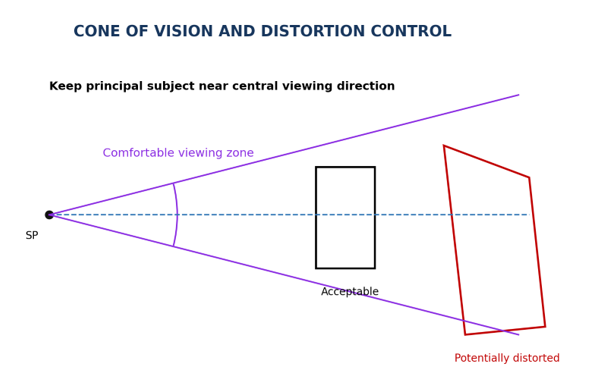
Practical Use |
Keep the principal subject reasonably close to the central viewing direction, especially in wide interiors, streetscapes and panoramic architectural compositions. |
12. Visual Rays
Visual rays are imaginary straight lines joining the Station Point to points on the object. They are fundamental to exact perspective construction because their intersections with PP identify where object points are transferred into the perspective field.
Projection Logic |
Object point → Visual ray → Picture Plane → Projector → Perspective point |
In plan-based perspective methods, visual rays are drawn from SP to important corners of the object. The piercing points on PP are then projected into the perspective view. This avoids guessing or directly measuring receding distances in the perspective drawing.
13. Vanishing Point and Measuring Point
13.1 Vanishing Point
A Vanishing Point is the apparent meeting point of a family of parallel receding lines. For horizontal lines, the vanishing point lies on the Horizon Line. Each distinct horizontal direction has its own vanishing point.
- One-point perspective: one principal receding family converges to one VP.
- Two-point perspective: two principal horizontal directions converge to VP₁ and VP₂.
- Three-point perspective: the two horizontal directions and the vertical direction each converge to a VP.
13.2 Measuring Point
A Measuring Point is a construction aid used in some perspective methods to transfer true or scaled dimensions along receding directions. It should not be confused with a Vanishing Point: a VP controls direction, whereas a measuring point assists in transferring distance.
Do Not Confuse |
Vanishing Point = direction. Measuring Point = transfer of distance. |
14. Types of Perspective
14.1 One-Point Perspective
One-point perspective is used when one principal face is parallel to PP and one major horizontal direction recedes away from the observer. The receding lines converge to a single principal VP. It is especially suitable for interiors, corridors, roads and strongly axial compositions.
14.2 Two-Point Perspective
Two-point perspective is used when the object is viewed from a corner and two horizontal directions recede. These directions converge toward two VPs located on the Horizon Line. Vertical edges normally remain vertical. It is widely used for building exteriors, residences, furniture and streetscapes.
14.3 Three-Point Perspective
Three-point perspective includes a third Vanishing Point for the vertical direction. Vertical lines therefore converge as well. It is appropriate for dramatic high-angle or low-angle views of towers, high-rise buildings and urban compositions.
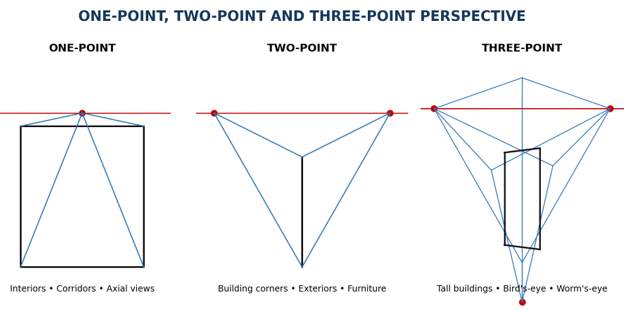
Selection Principle |
The number of vanishing points depends on orientation and viewing direction, not on the complexity of the object. |
15. Architectural Applications
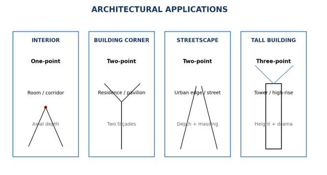
The most suitable type of perspective depends on the communication objective. The same building may be represented in different ways from different viewpoints.
Situation | Recommended Type | What It Communicates Best | Typical Example |
Frontal interior / corridor | One-point | Axial depth and spatial focus | Studio, lobby, hallway |
Building corner | Two-point | Massing and two adjoining façades | Residence, pavilion |
Street / urban edge | Two-point | Depth, rhythm and urban enclosure | Streetscape |
Tall building from low/high angle | Three-point | Height and dramatic viewpoint | Tower, high-rise |
Large complex from above | Three-point / bird’s-eye | Overall massing and spatial organisation | Campus / urban block |
16. Perspective as an Architectural Communication Tool
Perspective is not only a presentation technique. It is also a design-thinking tool. During design development, it allows the architect to evaluate massing, spatial sequence, scale, proportion and the relationship between built form and the observer.
- Design exploration – test different viewpoints and spatial compositions.
- Design evaluation – assess proportion, enclosure, scale and visual hierarchy.
- Communication – explain design intent to clients, juries and users.
- Interior representation – communicate furniture, openings and depth.
- Exterior representation – communicate form, façade relationships and context.
- Urban representation – communicate streetscape, public realm and spatial sequence.
Three Functions of Perspective |
VISUALISE → EVALUATE → COMMUNICATE |
17. Quick Revision
Term / Rule | Quick Recall |
SP | Observer position |
PP | Plane receiving the perspective image |
GP | Horizontal reference plane |
GL | PP ∩ GP |
EL | Observer eye height |
HL | Eye level represented on PP |
CP | Central viewing plane through SP |
CV | Where central viewing direction meets PP |
Visual Ray | SP to object point |
VP | Apparent meeting point of parallel receding lines |
Cone of Vision | Comfortable viewing field with limited distortion |
One-point | One principal receding direction |
Two-point | Two horizontal receding directions |
Three-point | Two horizontal + one vertical receding direction |
18. Check Your Knowledge
18.1 Short-Answer Questions
- 1. Define perspective drawing and state its importance in architectural communication.
- 2. Differentiate between perspective projection and metric projection.
- 3. Explain diminution and convergence with architectural examples.
- 4. Define Station Point, Picture Plane, Ground Plane, Ground Line and Horizon Line.
- 5. Explain the relationship between Eye Level and Horizon Line.
- 6. What is the Cone of Vision and why is it important?
- 7. Explain the role of visual rays in perspective construction.
- 8. What is a Vanishing Point? Why do horizontal VPs lie on the Horizon Line?
- 9. Differentiate between one-point, two-point and three-point perspective.
- 10. Explain how changing the Station Point affects the resulting perspective view.
18.2 MCQs
- The exact position of the observer is called:
- a) Ground Line b) Station Point c) Picture Plane d) Vanishing Point
- The Horizon Line represents:
- a) Ground level b) Object height c) Observer’s eye level d) Picture Plane
- In two-point perspective, the two principal horizontal directions generally converge toward:
- a) One VP b) Two VPs c) Three VPs d) No VP
- The intersection of PP and GP is called:
- a) Ground Line b) Horizon Line c) Central Plane d) Cone of Vision
- A family of parallel horizontal lines having the same spatial direction shares:
- a) The same Station Point b) The same Vanishing Point c) The same Ground Line d) Different Picture Planes
- Moving the Station Point very close to the object generally produces:
- a) Flatter perspective b) Stronger perspective convergence c) Orthographic projection d) No change
18.3 Suggested Drawing Exercise
Prepare a labelled conceptual sheet showing SP, PP, GP, GL, HL, CP, CV, Cone of Vision, Visual Rays and a Vanishing Point. Below it, draw simple thumbnail examples of one-point, two-point and three-point perspective and write one architectural application of each.
Summary
Unit I establishes the vocabulary and visual logic of perspective drawing. A perspective view is created by the relationship between the object, the observer and the picture plane. The Station Point determines the viewpoint; the Horizon Line records the eye level; visual rays locate projected points; and vanishing points control receding directions. Understanding these principles is essential before beginning exact one-point and two-point perspective construction in the subsequent units.
Final Takeaway |
Perspective is not simply “drawing in 3D.” It is a controlled geometric system for representing how space appears from a selected viewpoint. |
How useful was this post?
Click on a star to rate it!
Average rating 0 / 5. Vote count: 0
No votes so far! Be the first to rate this post.


