
UNIT 3: | AR503 | CONSTRUCTION PRACTICE, METHODS & EQUIPMENT

3.1 Understanding Modern Construction Practice
Construction practice is the way in which a design is physically converted into a building. Traditional construction depends heavily on activities performed directly at the site—setting out, formwork, reinforcement, mixing, casting, curing and finishing. Modern construction does not eliminate these activities; rather, it reorganizes them through mechanisation, factory production, improved materials, better logistics and systematic quality control.
The central idea is productivity with predictable quality. A project becomes ‘advanced’ not merely because it uses an expensive machine, but because materials, labour, equipment, information and time are coordinated as a system. For example, precast construction transfers much of the wet work from the site to a controlled production yard, while ready-mixed concrete transfers batching and mixing to a specialised plant.
Learning connection |
Modern construction should be understood as a shift from isolated site operations to an integrated production system: DESIGN → MATERIALS → MANUFACTURE → LOGISTICS → ASSEMBLY → QUALITY & SAFETY. |
3.1.1 Role of Modern Materials
Modern materials support faster, lighter, more durable and more predictable construction. High-performance concrete can provide improved strength and durability; fibre-reinforced materials can control cracking or reduce weight; engineered panels can speed enclosure work; and advanced sealants and connection materials help prefabricated components perform as a complete building system.
The important point for an architect is that material selection affects the construction method. A lightweight panel may permit smaller lifting equipment; a factory-finished façade panel may reduce scaffolding and wet finishing; and high-early-strength concrete may shorten production cycles. Therefore, materials and methods should be selected together rather than independently.
Material / system | Construction significance |
High-performance concrete | Higher strength/durability can permit efficient structural sections and demanding exposure conditions. |
Fibre-reinforced concrete | Fibres help control cracking and improve toughness depending on fibre type and dosage. |
Engineered / prefabricated panels | Reduce site fabrication and accelerate enclosure or partition work. |
FRP products | Lightweight, corrosion-resistant components useful in selected strengthening and building applications. |
Advanced sealants / grouts | Important for joints, bearings and connections in prefabricated construction. |
Exam-ready idea |
Modern materials are valuable when they improve the performance of the construction system—speed, durability, quality, weight, safety or maintainability. Do not write only a list of material names; relate each material to its construction benefit. |
3.2 Precast Construction: The Core Idea
In conventional cast-in-situ reinforced concrete construction, the structural member is cast at the same location where it will remain in the completed building. Precast construction separates these two locations. Beams, columns, slabs, wall panels, stairs or other components are manufactured in a casting yard or factory, allowed to develop the required strength, and then moved to their final position.
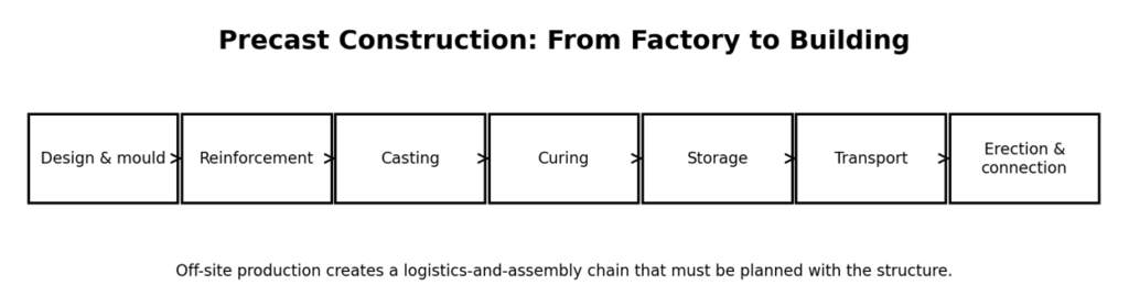
This simple change creates an entirely different construction logic. Because the component is produced away from its final position, the project must plan not only casting but also lifting, temporary storage, transportation, erection, alignment and connection. Thus, precasting is simultaneously a structural system, a manufacturing process and a logistics operation.
3.2.1 Why Precasting Can Save Time
In cast-in-situ construction, many activities occur sequentially: formwork is erected, reinforcement is placed, concrete is cast, strength develops, formwork is removed, and only then can subsequent work proceed. In precast construction, factory production can occur at the same time as foundations and other site activities. This parallel working is a major reason for time saving.
Factory conditions can also improve dimensional control, mould reuse, concrete batching, compaction, curing and surface finish. However, these advantages are achieved only when design is repetitive enough, connections are properly detailed, transportation is feasible and lifting operations are planned.
Understand before remembering |
PRECAST ≠ simply ‘concrete made in a factory’. The system succeeds only when manufacture + storage + transport + erection + connections are designed as one continuous process. |
3.3 Manufacture of Precast Concrete Components
Manufacturing begins with production planning. The required component geometry, reinforcement, inserts, lifting points, tolerances and finish must be known before the mould is prepared. Repetition is particularly important because a mould becomes economical when it can be reused for several similar components.
3.3.1 Typical Manufacturing Sequence
The mould is first cleaned and prepared so that dimensions and surface quality are controlled. Reinforcement cages, embedded plates, sleeves, conduits and lifting anchors are then fixed in their correct positions. Concrete is placed and compacted to remove entrapped air and ensure full contact around reinforcement and inserts. After finishing, the component is cured until it has sufficient strength for demoulding and handling.
Demoulding is a critical stage because a component may be structurally adequate in its final position but vulnerable while being lifted. After demoulding, the unit is inspected for dimensions, surface defects, inserts and identification before it is released for storage or dispatch.
Stage | What happens | Why it matters |
Mould preparation | Clean, dimension-check and apply suitable release treatment. | Controls geometry and surface finish. |
Reinforcement & inserts | Fix reinforcement, lifting anchors, sleeves and embedded plates. | Ensures structural action and future lifting/connection. |
Concrete placement | Batch, place and compact concrete. | Controls strength, density and finish. |
Curing | Maintain suitable conditions for strength development. | Reduces early-age defects and enables safe handling. |
Demoulding | Remove component after adequate handling strength. | Prevents cracking or edge damage. |
Inspection | Check dimensions, finish, inserts and identification. | Stops defective units from entering the erection chain. |
Likely 5-mark answer |
If asked ‘Explain manufacture of precast components’, write a short definition, draw the production sequence, then explain mould preparation → reinforcement/inserts → concreting → compaction → curing → demoulding → inspection. End with the importance of factory quality control. |
3.4 Storage of Precast Components
A precast element does not always travel directly from the mould to the building. It may remain in a storage yard until the site is ready. Storage is therefore a structural issue, not merely a space-management issue. A long beam or panel supported at the wrong locations can develop bending stresses different from those for which it was designed.
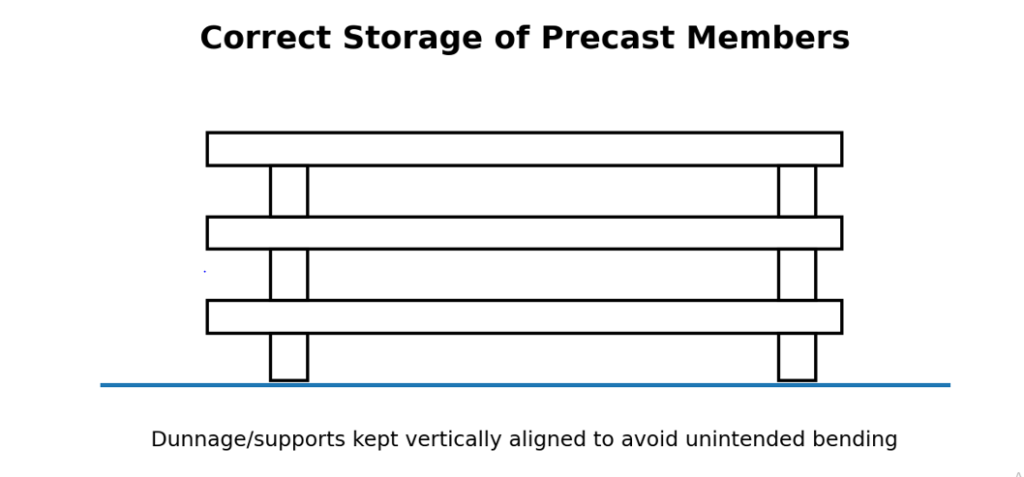
Members should be placed on firm, level supports or dunnage at positions appropriate to the element. When units are stacked, supports should generally be aligned vertically so that loads pass through the stack without creating unintended bending. Identification marks should remain visible and sufficient space should be provided for lifting equipment.
- . Provide stable, level ground and adequate drainage.
- . Support components at designed or approved points.
- . Keep stacked supports vertically aligned where applicable.
- . Prevent edge, corner and finished-surface damage.
- . Maintain identification and erection sequence.
- . Provide safe access for cranes and handling equipment.
3.5 Transportation of Precast Components
Transportation links factory production with site erection. The size and weight of a component may be structurally possible but logistically impractical. Architects and engineers must therefore consider road width, turning radius, bridge/route restrictions, vehicle capacity, loading orientation and site entry while deciding component dimensions.
During transport, members experience vibration, braking, acceleration and temporary support conditions. They must therefore be restrained against sliding or overturning and supported so that transport stresses remain acceptable. Large panels may require specialised frames, while long beams may require trailers capable of accommodating their length.
Design lesson |
A precast component should be designed not only for its FINAL POSITION but also for its TEMPORARY CONDITIONS: demoulding, lifting, storage, transport and erection. |
3.6 Erection of Precast Components
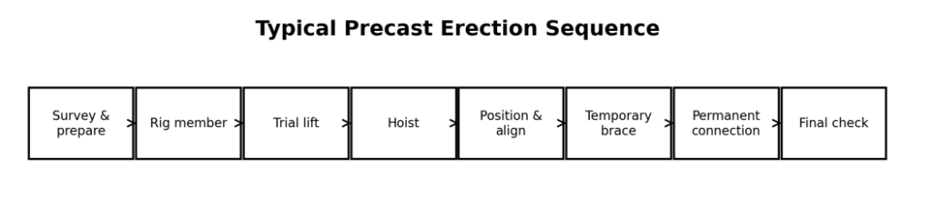
Erection is the stage at which manufactured units become a building. The operation normally begins with survey control and preparation of bearings or connection locations. A crane lifts the element from the delivery vehicle or storage area, guides it into position, and holds it while workers align and temporarily stabilise it.
Permanent structural action should not be assumed until the specified connections, grouting, welding, bolting, in-situ stitching or other connection work has been completed. Temporary bracing is especially important for columns and wall panels because an apparently upright component can remain unstable before the structural system is tied together
3.6.1 Connections: Why They Matter
Precast construction divides a building into separate manufactured pieces; connections restore continuity between those pieces. Depending on the structural system, connections may use bolts, welds, dowels, reinforcement continuity, grouted sleeves, bearing pads or in-situ concrete. Their purpose may include transferring vertical load, shear, bending, tension or horizontal forces while also accommodating construction tolerances.
Poorly conceived connections can cancel the advantages of precasting. A good connection should be structurally reliable, constructible, inspectable and compatible with the erection sequence.
Exam-ready idea |
Precast construction is often judged by its CONNECTIONS. Manufacture creates the pieces; connections make the pieces behave as a building. |
3.7 Moulds and Formwork for Precast Production
A mould gives a precast component its geometry, dimensions and surface finish. Because the same mould may be reused many times, mould accuracy directly affects the consistency of production. Moulds may be made from steel, timber/plywood, concrete, polymeric materials or combinations depending on repetition, required finish, shape and economy.
Steel moulds are suitable for high repetition because they are durable and dimensionally stable, but they require higher initial investment. Timber or plywood moulds are easier to modify and economical for limited repetition, but their service life and dimensional stability are generally lower.
Mould type | Best suited to | Main consideration |
Steel | High repetition and accurate factory production | High initial cost; durable and reusable. |
Timber / plywood | Small series or changing geometry | Easy to fabricate; lower reuse. |
Concrete casting bed | Long linear or repetitive units | Rigid, stable production surface. |
Special / flexible mould | Complex architectural geometry | Useful for special forms but cost and handling require study. |
Release agents should assist demoulding without damaging the surface or interfering with later finishes. Joints in the mould must prevent unacceptable grout leakage, and dimensional checks should be carried out before casting.
3.8 Scaffolding: Temporary Works That Enable Permanent Construction
Scaffolding is a temporary structure that provides working platforms and access for workers, materials and tools at height. Although temporary, it must be treated as an engineered system because failure can cause falls, collapse and damage to the permanent work.
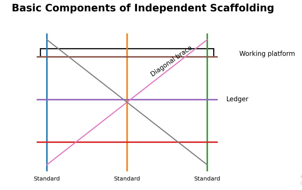
A typical independent scaffold contains vertical standards, horizontal ledgers, transoms supporting the platform, diagonal bracing for stability, base plates/sole boards, guardrails and toe boards. Ties may connect the scaffold to the building where required.
3.8.1 Common Types of Scaffolding
Type | Basic idea | Typical relevance |
Single / putlog scaffold | One main row of standards with support related to the wall. | Traditional masonry work. |
Double / independent scaffold | Two rows of standards form a more independent framework. | Stonework and situations needing independent support. |
Cantilever scaffold | Working platform supported from needles/cantilevers. | Where ground near façade cannot support standards. |
Suspended scaffold | Platform suspended from roof/upper structure. | Façade maintenance, painting and selected external works. |
Mobile scaffold | Scaffold tower mounted on wheels/castors. | Short-duration work requiring repeated relocation. |
System / modular scaffold | Prefabricated standards, ledgers and connectors. | Fast repetitive assembly on modern projects. |
3.8.2 Safety Logic of Scaffolding
Scaffold safety depends on four connected ideas: a stable base, adequate bracing and tying, a safe working platform, and controlled access. Removing one of these can make the entire system unsafe. Overloading platforms, removing braces, using damaged components or shifting mobile scaffolds while occupied can create serious hazards.
Remember |
Scaffolding should be inspected after erection and when conditions may have affected its stability. Temporary works deserve the same disciplined planning as permanent works. |
3.9 Safety During Erection and Dismantling
Erection work combines height, suspended loads, temporary instability and heavy equipment. The safest approach is therefore to plan the operation before the crane begins lifting. A lifting plan should identify the component weight, lifting points, crane capacity and radius, rigging arrangement, exclusion zone, communication method and temporary stability requirements.
Workers should never remain beneath suspended loads. Tag lines may be used where appropriate to control rotation from a safe position. Components should be temporarily braced before the crane releases them, and permanent connections should be completed in the specified sequence.
3.9.1 Dismantling Safety
Dismantling is not simply erection in reverse without thought. Removing a brace, tie or temporary support changes the stability of the remaining system. The sequence must therefore ensure that the part left standing remains stable at every stage. Materials should be lowered in a controlled manner rather than dropped.
Safety principle |
At every stage ask: ‘If this support, brace or lifting hook is removed now, what keeps the remaining component stable?’ This question captures the logic of safe erection and dismantling. |
3.10 Construction Equipment
Construction equipment converts energy into useful site work. Mechanisation becomes valuable when it increases output, reduces excessive manual handling, improves precision or makes a task possible at the required scale. Equipment should therefore be classified by the function it performs rather than learned as an unrelated list of machine names.
Function | Typical equipment | Construction purpose |
Earthwork | Excavator, bulldozer, loader | Excavate, push, load and shape soil. |
Haulage | Dump truck, tipper | Move soil, aggregate and debris. |
Lifting | Tower crane, mobile crane, hoist | Move structural components/materials vertically and horizontally. |
Concrete production | Batching plant, mixer, transit mixer | Measure, mix and transport concrete. |
Concrete placement | Concrete pump, bucket | Deliver concrete to point of placement. |
Compaction | Roller, plate compactor, concrete vibrator | Increase density of soil or concrete. |
Foundation work | Piling rig | Install piles or deep-foundation elements. |
The architect should understand equipment because machine requirements affect access roads, crane positions, staging areas, basement ramps, temporary works and construction sequencing. Equipment planning is therefore connected with site planning.
3.11 Ready-Mixed Concrete (RMC) Plant
Ready-mixed concrete is concrete produced under controlled batching conditions and delivered in a fresh state for placement. Its key advantage is not simply that concrete arrives in a truck; the important difference is controlled proportioning and production.
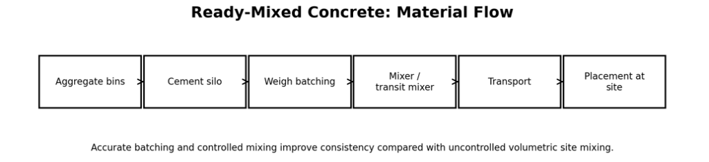
Aggregates are stored in separate bins, while cementitious materials are commonly stored in silos. Water and admixtures are measured according to the approved mix. The batching system weighs the constituents, after which they are mixed in a central mixer or introduced into a transit-mixing system depending on plant configuration. The concrete is then transported to the site and placed before loss of workability makes placement unacceptable.
3.11.1 Why RMC Improves Control
Small site mixing often depends on variable volumetric measurement, changing moisture conditions and operator judgement. A properly managed RMC plant uses controlled batching, calibrated equipment and recorded mix proportions, which can improve consistency. It also reduces the need for large-scale storage of cement and aggregates at congested urban sites.
RMC still requires careful coordination. Travel time, traffic, temperature, slump/workability, pumping capacity and the rate of placement must be matched. A high-capacity plant offers little benefit if trucks queue for long periods because the site cannot receive concrete fast enough.
RMC advantage | Why it occurs |
Consistency | Controlled weighing and batching reduce variation. |
Speed | Large quantities can be supplied continuously when plant and site are coordinated. |
Cleaner site | Less on-site storage and mixing of cement/aggregate. |
Quality records | Plant production can be monitored and documented. |
Reduced site labour | Major batching/mixing operations occur away from the placement location. |
Likely 5-mark answer |
For ‘Explain an RMC plant’, define RMC, draw the material-flow diagram, explain aggregate bins + cement silo + weighing/batching + mixing + transit + placement, then state advantages and one limitation such as transport/time coordination. |
3.12 Selection of Construction Equipment
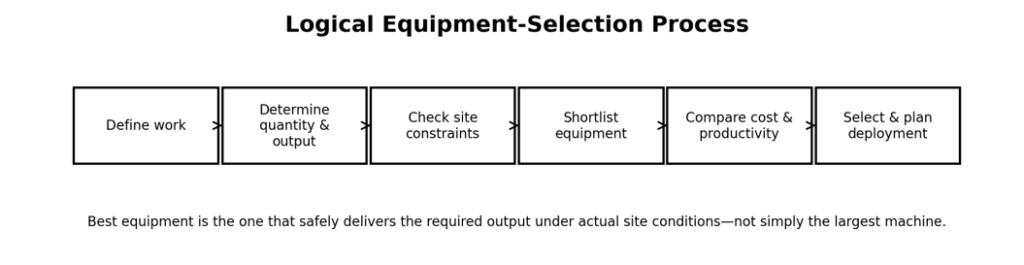
Equipment selection is an engineering and management decision. Choosing the largest or newest machine is not necessarily economical. The selected equipment must match the nature of work, required output, site conditions, project duration, availability of operators, maintenance support and total cost.
For example, a tower crane may provide excellent coverage on a high-rise project but may be unnecessary on a low-rise project with dispersed work fronts. A mobile crane may offer flexibility for short-duration precast erection, while a tower crane may be justified where repeated lifting continues throughout the structural cycle.
3.12.1 Major Selection Factors
Factor | Question to ask |
Nature of work | What operation must the equipment perform? |
Quantity / productivity | How much output is required per hour/day? |
Site conditions | Is there enough access, turning space, bearing capacity and headroom? |
Lift / reach / depth | Can the equipment physically reach the work zone at the required capacity? |
Project duration | Is purchase justified or is hiring more economical? |
Availability & service | Are operators, spare parts, fuel/power and maintenance support available? |
Safety | Can the equipment operate with acceptable risk and exclusion zones? |
Economy | What is the cost per unit of useful output, including idle time and mobilisation? |
A useful economic comparison is cost per unit of production rather than purchase price alone. A cheaper machine with low output and frequent breakdowns may cost more per cubic metre excavated or per tonne lifted than a more productive alternative.
3.13 Connecting the Unit: One Construction-System View
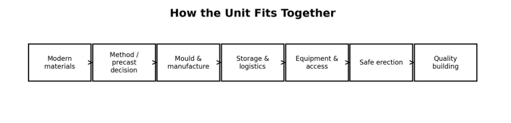
The topics in this unit are not separate chapters of facts. They describe one construction system. Modern materials influence component design; moulds convert designs into repeatable precast units; storage and transport preserve those units until required; cranes and scaffolds provide access and lifting; erection safety controls temporary conditions; RMC and other equipment mechanise site production; and equipment selection ensures that the chosen method is practical and economical.
3.14 Examination-Oriented Revision
3.14.1 High-Value Concepts to Understand
- . Why precast construction creates a manufacture–storage–transport–erection chain.
- . Why temporary conditions can govern handling and erection of precast members.
- . Why mould accuracy and reuse affect precast quality and economy.
- . Why scaffolding is an engineered temporary-work system rather than only a working platform.
- . Why RMC quality depends on controlled batching and logistics.
- . Why equipment selection is based on required output and site conditions rather than machine size alone.
3.14.2 Important 5-Mark Questions
- . Explain the complete process of manufacture, storage, transportation and erection of precast concrete components with suitable diagrams.
- . Explain different types and essential components of scaffolding. Discuss important safety requirements.
- . Explain the working of a Ready-Mixed Concrete plant with a neat flow diagram. State its advantages and limitations.
- . Discuss the factors governing selection of construction equipment for a building project.
- . Explain safety precautions during erection and dismantling of precast or temporary construction systems.
- . Explain the role of moulds in precast construction and compare common mould materials.
3.14.3 Short-Answer / 2½-Mark Questions
- . Differentiate cast-in-situ and precast construction.
- . What is dunnage and why is support alignment important in precast storage?
- . State four considerations during transportation of precast members.
- . What is temporary bracing and why is it required during erection?
- . Name the principal components of an independent scaffold.
- . What is RMC? State two advantages.
- . List four factors affecting equipment selection.
3.14.4 How to Write a Strong 5-Mark Answer
A strong answer should normally contain four elements: (1) a clear definition or introductory paragraph, (2) a logical explanation of the process or principle, (3) a neat labelled diagram or table wherever relevant, and (4) a short concluding statement on advantages, safety or application. Avoid writing only disconnected bullets unless the question specifically asks for a list.
Final revision chain |
PRECAST: manufacture → handling → storage → transport → erection → connection. | RMC: store → weigh → mix → transport → place. | EQUIPMENT: work → output → site constraints → alternatives → cost/productivity → selection. |
3.15 Suggested Reading
Students should use these notes as the primary examination-oriented reading for Unit 3 and consult standard construction-technology texts, relevant BIS standards, equipment manuals and project specifications for deeper technical values, detailed design requirements and safety procedures. Exact capacities, tolerances and statutory safety provisions must always be verified for the actual project and jurisdiction.
How useful was this post?
Click on a star to rate it!
Average rating 0 / 5. Vote count: 0
No votes so far! Be the first to rate this post.


