
CHAPTER 5 Pneumatic Structures and Surface-Active Structural Systems

Prescribed syllabus
Domes, shells, folded plates and other surface-active structures; folded plates and barrel shells; hyperbolic paraboloids; domes in reinforced cement concrete (RCC); geodesic domes; and space frames.
Terminology note: The university unit is titled “Pneumatic Structures”, although most listed topics are non-pneumatic. Air-supported and air-inflated systems are explained separately in §5.9.
5.1 Introduction to long-span structural systems
Long-span structures create substantial unobstructed interior spaces in auditoriums, stadiums, terminals, exhibition halls and industrial buildings. Compared with ordinary beam-and-slab systems, shells, folded plates, domes and three-dimensional frames exploit geometry to manage loads and control deflection. The structural system must be chosen in conjunction with architectural form, material availability, erection methodology and maintenance.
- Surface-active: curved or folded plates distribute forces across a continuous surface.
- Vector-active: triangulated frames transfer forces mainly through interconnected linear members.
- Pneumatic: pressurised air stabilises a membrane or inflated structural element.
5.2 Structural principles and load transfer
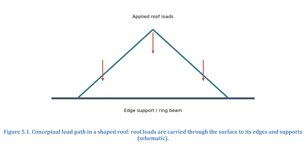
A surface-active system ideally carries loading through in-plane compression, tension and shear (membrane action). Real structures also develop bending, especially around openings, concentrated loads, edge beams and discontinuities. Shape and boundary conditions are therefore essential to structural performance.
Architectural implications
Long-span systems influence roof profile, clear height, daylight openings, drainage slopes, acoustic surfaces, construction staging and the position of structural supports. Structural efficiency cannot be inferred from appearance alone; detailed engineering analysis is necessary.
5.3 Folded plate structures
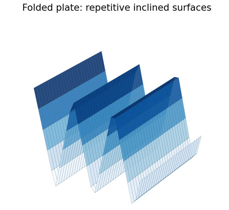
Folded plates consist of flat planar elements joined along longitudinal fold lines. The corrugated configuration increases effective stiffness compared with an equivalent flat plate and permits loads to be redistributed through plate bending, in-plane action and fold connections.
Components and structural action
Inclined plates form the primary surface; fold junctions ensure interaction between adjacent plates; edge beams or diaphragms support force transfer. The design must address plate thickness, fold geometry, reinforcement or connection detailing, and edge restraint.
Types and applications
V-fold, zigzag, trough and non-prismatic folded roofs can be made in cast-in-situ RCC, precast concrete, steel or timber. They are suited to halls, factories, schools and institutional roofs with repeated bays.
Construction sequence
Establish supports and geometry; install inclined formwork or prefabricated units; position reinforcement and joint details; cast or connect plates; cure and remove temporary supports in the approved sequence; finish waterproofing and drainage.
Advantages and limitations
Advantages include repetitive fabrication, distinctive roof expression and improved geometric stiffness. Limitations include complicated formwork, fold reinforcement, waterproofing details and difficult penetrations.
5.4 Barrel shell structures
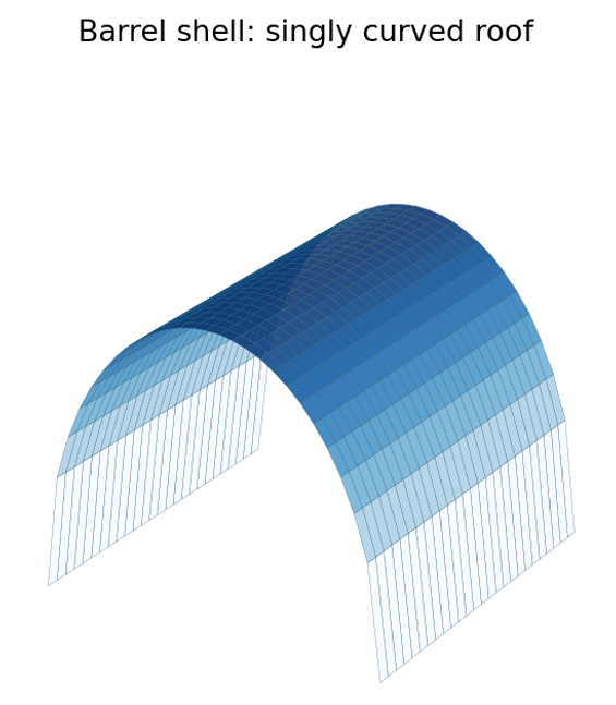
A barrel shell is a roof with a predominantly cylindrical curved surface. It is singly curved, unlike a hypar. It may act through longitudinal and transverse membrane forces, shear and bending; behaviour depends on span, length, edge members and end supports.
Configurations
Single barrel shells, multiple adjacent barrels, short barrels and long barrels are possible. Materials include RCC, precast units, timber and steel-supported curved roof systems.
Design and construction
The curvature and rise affect stiffness, usable volume and drainage. RCC versions require accurate curved centring, reinforcement placement, concrete curing and carefully detailed edge beams. Openings should be assessed for their effect on the shell load path.
Applications
Aircraft hangars, railway platforms, factories, assembly halls and exhibition buildings. Their advantages include continuous curved roofing and unobstructed space; limitations include formwork cost and sensitive edge conditions.
5.5 Hyperbolic paraboloid shells
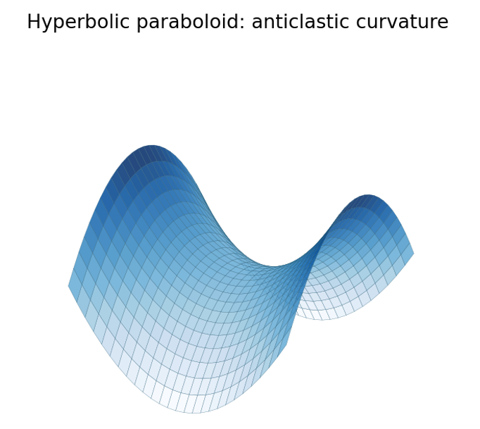
A hyperbolic paraboloid (hypar) is an anticlastic, saddle-shaped surface: it curves upward in one principal direction and downward in the other. A standard mathematical form is z = x²/a² − y²/b². A key construction advantage is that a hypar can be generated using straight lines, permitting straight formwork members in some configurations.
Structural behaviour
The geometry enables membrane tension, compression and shear, with bending developing near boundaries and local disturbances. Supports, edge beams and corners may carry substantial concentrated forces.
Construction and use
Set out the ruled surface; assemble straight-line formwork; install reinforcement; cast and cure the thin shell; remove temporary works only when adequate strength is reached. Hypars are used for expressive canopies, pavilions, entrances and halls. Félix Candela is a major reference for thin-shell concrete design.
5.6 Reinforced-concrete domes
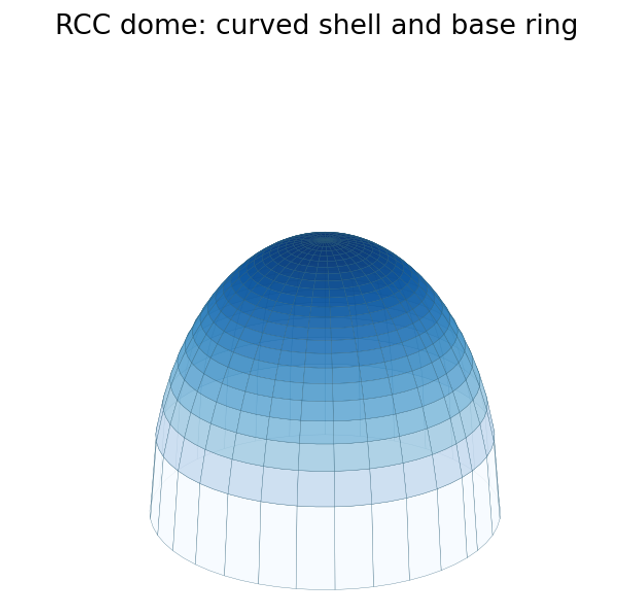
An RCC dome is a curved shell enclosing space around a central region or axis. Main parts include crown, meridional shell surface, springing and supporting ring beam or perimeter structure. Spherical, segmental, ellipsoidal and ribbed domes are common variants.
Load transfer
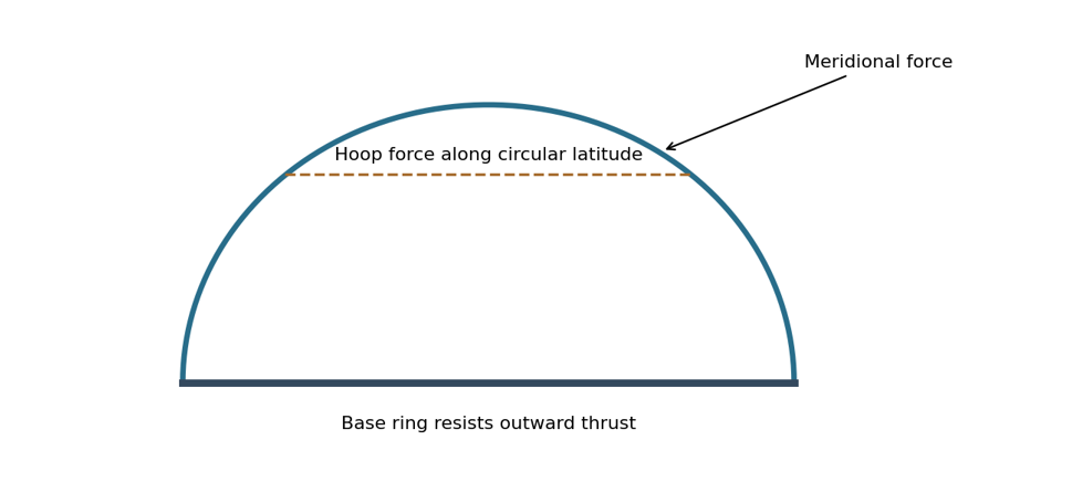
Under symmetric gravity loading, meridional forces are typically compressive. Hoop forces can change from compression to tension depending on position and dome geometry; the lower portion of some spherical domes develops hoop tension. A designed tension ring or ring beam may resist outward thrust.
Construction
Construct supports and ring beam; erect centring; place reinforcement and concrete in an engineered sequence; cure; dismantle centring at the specified strength. Critical details include waterproofing, shell openings, base restraint and seismic response.
5.7 Geodesic domes
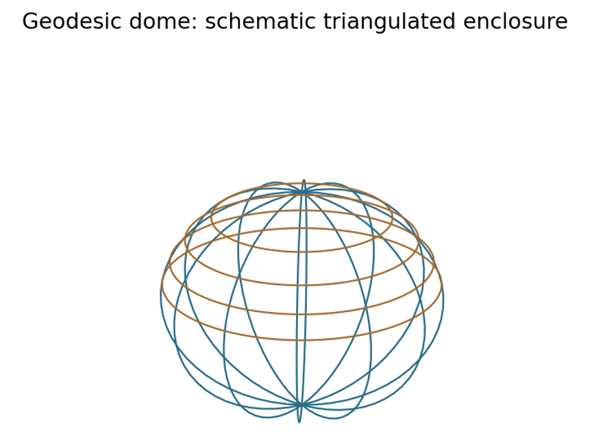
A geodesic dome is a dome-like three-dimensional frame formed from many short struts joined at nodes, commonly in a triangulated pattern. It approximates a curved enclosure through interconnected polygonal or triangular units. Buckminster Fuller popularised geodesic dome applications.
Structural system
Struts and joints transfer tension and compression through the network; the real force distribution also depends on joint rigidity and cladding loads. Fabrication precision and node geometry are especially important.
Assembly and architectural implications
Prepare the geometry and member schedule, fabricate struts and nodes, assemble sequential rings or modules, brace during erection, and apply enclosure cladding. Advantages include lightweight potential and prefabrication. Challenges include joint complexity, irregular openings and weather sealing.
5.8 Space frame structures
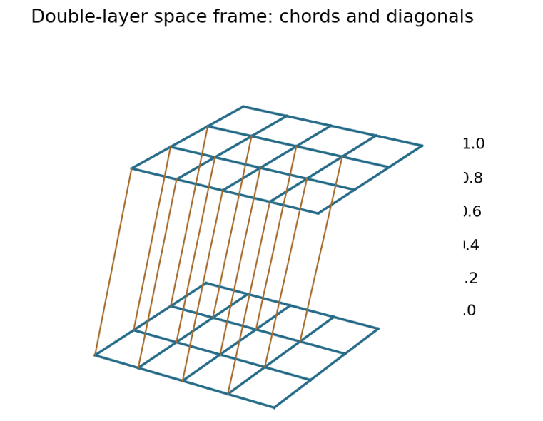
A space frame is a three-dimensional network of structural members and nodes. A double-layer system comprises upper and lower chords linked by diagonal web members. Triangulation and three-dimensional depth allow roof loads to be distributed in several directions.
Types and load path
Single-layer, double-layer, triple-layer and curved space frames are used. In an ideal pin-jointed model, members carry primarily axial tension or compression, although real connections and applied loads can introduce bending.
Fabrication and erection
Steel or aluminium tubes are fabricated to specified lengths; nodes may be bolted, welded or proprietary; modules are assembled at ground level or in situ; cranes lift segments onto prepared supports. Connection inspection, temporary bracing, corrosion protection and fire performance require attention.
Applications
Airport terminals, stadia, transport concourses, atriums and exhibition halls. Large spans and modular prefabrication are advantages; many nodes and demanding maintenance access are limitations.
5.9 Pneumatic structures
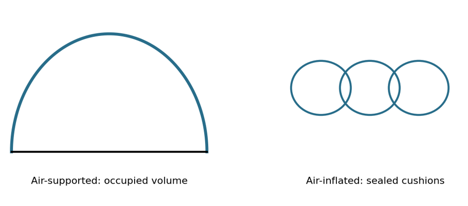
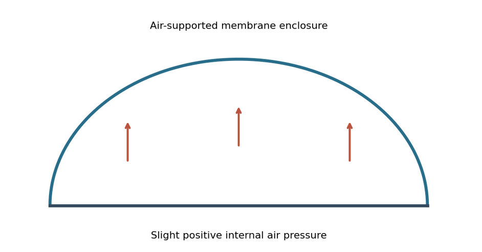
Unlike shells and space frames, pneumatic structures rely on controlled air pressure. An air-supported building uses slightly elevated air pressure in the occupied enclosure to stabilise its membrane. Air-inflated systems pressurise discrete cushions or tubes, which can be combined with independent structural framing.
Pressure relationship
The pressure difference is ΔP = P_inside − P_outside. Pressure requirements must be determined from wind, snow or rain loads where applicable, geometry, anchorage and the membrane design. Common materials include PVC-coated polyester, PTFE-coated glass fibre and ETFE film.
Design considerations
Airlocks, blowers, standby power, pressure sensors, anchorage, condensation control, emergency evacuation and maintenance are essential for air-supported buildings. Air-inflated cushions need controlled pressure and leak management.
5.10 Comparative selection of systems
System | Primary action | Common materials | Applications |
Folded plate | Plate + in-plane forces | RCC, steel, timber | Institutional roofs |
Barrel shell | Curved shell action | RCC, timber | Hangars, platforms |
Hypar | Anticlastic shell action | RCC, composites | Canopies, halls |
RCC dome | Meridional + hoop forces | Reinforced concrete | Religious/civic halls |
Geodesic dome | Triangulated member forces | Steel, timber | Enclosures, pavilions |
Space frame | 3D axial member network | Steel, aluminium | Terminals, arenas |
Pneumatic | Air-pressure membrane | ETFE, coated fabrics | Temporary venues, cushions |
5.11 Architectural case studies
Sydney Opera House, Australia
Precast concrete roof ribs and panels derived from spherical geometry; a useful case for geometry, prefabrication and structural expression, but not a conventional thin membrane shell.
Palazzetto dello Sport, Rome
Pier Luigi Nervi’s reinforced-concrete sports hall illustrates structural pattern, prefabricated components and an expressive dome roof.
Montreal Biosphere, Canada
A geodesic enclosure associated with Buckminster Fuller; useful for understanding modular triangulated framing and connection networks.
Eden Project, United Kingdom
Interconnected steel enclosure frameworks with ETFE cushions demonstrate integration of lightweight cladding and complex three-dimensional geometry.
5.12 Materials, connections and construction methods
- Cast-in-situ RCC: curved or folded formwork, reinforcement, casting sequence, curing and removal of temporary supports.
- Precast concrete: dimensional accuracy, transport constraints, lifting inserts, connection design and joint weatherproofing.
- Steel and aluminium framing: member fabrication, bolted/welded nodes, temporary bracing, corrosion protection and erection sequence.
- Membranes: fabric cutting patterns, tensioning, edge clamping, air supply and monitoring equipment.
5.13 Design considerations
- Clear span, loading, deflection and vibration criteria.
- Structural geometry, support layout, foundations and lateral stability.
- Availability of skilled contractors, fabrication and erection equipment.
- Integration of skylights, drainage, HVAC, lighting and acoustics.
- Weatherproofing, durability, access for inspection and life-cycle costs.
- Embodied carbon, material efficiency and reuse potential.
5.14 Worked numerical examples
Example 1: Rise-to-span ratio
A barrel shell spans 24 m and rises 6 m. Rise-to-span ratio = 6/24 = 0.25 = 1:4.
Example 2: Dome surface area
For a hemisphere of radius 10 m, curved area A = 2πr² = 2 × π × 10² ≈ 628.32 m².
Example 3: Approximate RCC volume
For a thin hemispherical shell with radius 10 m and uniform nominal thickness 0.10 m, V ≈ A × t = 628.32 × 0.10 = 62.83 m³. Excludes ribs, ring beams and openings.
Example 4: Space-frame grid
A 24 × 18 m roof using 3 × 3 m planning modules has (24/3) × (18/3) = 8 × 6 = 48 plan modules. This is not a member or node count.
5.15 Tutorial and practical exercises
Exercise A: Comparative A3 sheet
Draw labelled structural sketches of folded plate, barrel shell, hypar, RCC dome, geodesic dome and space frame. Annotate loads, support positions, typical materials and one construction challenge for each.
Exercise B: Long-span hall proposal
For a 30 × 40 m multipurpose hall, choose one long-span system; develop a conceptual roof plan and section; indicate support positions, force flow, material and erection strategy. Submit two A3 sheets.
Exercise C: Geodesic model
Build a triangulated dome model using struts and nodes. Record member types, connection details, assembly sequence and observed stability.
5.16 Examination-oriented questions
Short-answer questions
- Define a surface-active structural system.
- Explain the difference between a barrel shell and a hypar.
- What are fold lines in folded plate construction?
- Differentiate meridional and hoop forces.
- State the purpose of a ring beam in an RCC dome.
- What is a geodesic dome?
- Identify upper chord, lower chord and web members in a space frame.
- Differentiate air-supported and air-inflated structures.
Descriptive questions
- Explain the load-transfer mechanism and construction of folded plates with a labelled sketch.
- Describe barrel shells and hypar shells, comparing geometry and construction methods.
- Explain RCC dome behaviour under gravity loads with meridional and hoop force diagrams.
- Describe geodesic dome construction and discuss its advantages and limitations.
- Illustrate a double-layer space frame and explain its components and erection.
- Discuss pneumatic membrane structures with air-supported and air-inflated examples.
5.17 Suggested teaching schedule
Session | Topic | Hours |
1 | Introduction and surface action | 2 |
2 | Folded plates | 2 |
3 | Barrel shells and hypars | 2 |
4 | RCC domes | 2 |
5 | Geodesic domes | 2 |
6 | Space frames and pneumatic systems | 2 |
7 | Case studies, tutorials and review | 2 |
Total suggested: 14 contact hours. Confirm against the approved unit-wise teaching allocation.
5.18 Learning outcomes
- Identify and classify the principal long-span structural systems.
- Explain how shell curvature, folding and triangulation affect force transfer.
- Illustrate key components, supports and construction sequences.
- Compare the suitability of systems for large public and institutional buildings.
- Develop a conceptual long-span structural proposal with explanatory sketches.
5.19 Recommended references
- Engel, H. Structure Systems. Hatje Cantz.
- Schodek, D. L., & Bechthold, M. Structures. Pearson.
- Salvadori, M., & Heller, R. Structure in Architecture.
- Ching, F. D. K., Onouye, B. S., & Zuberbuhler, D. Building Structures Illustrated. Wiley.
- IS 456 (plain and reinforced concrete); IS 800 (steel construction); applicable current Indian loading and seismic standards. Verify current editions before professional use.
Chapter summary
Folded plates and shells use geometry to mobilise plate and membrane action; domes develop meridional and hoop forces; geodesic domes and space frames distribute forces through connected members; and pneumatic structures depend on controlled air pressure. Selection must integrate architecture, structural engineering, fabrication, construction sequencing and maintenance.
How useful was this post?
Click on a star to rate it!
Average rating 0 / 5. Vote count: 0
No votes so far! Be the first to rate this post.


